- 54 -
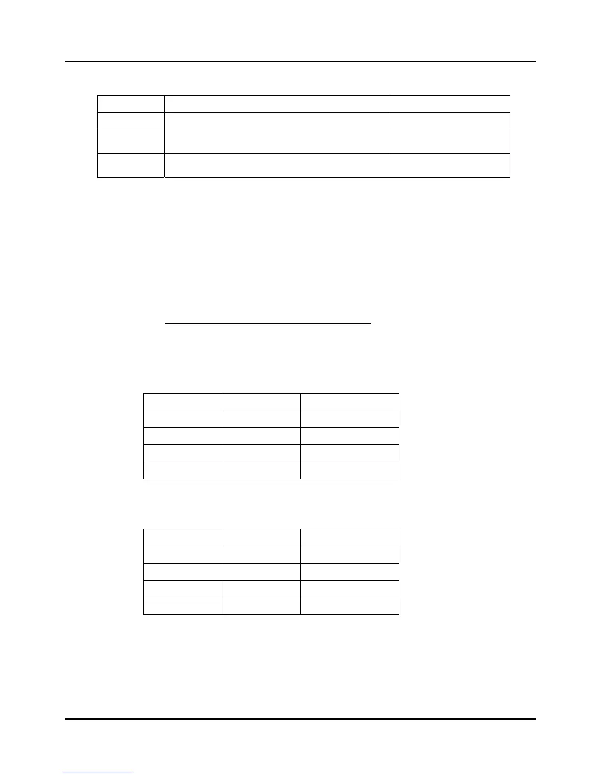
ITEM Description Remarks
FIX In operation of FIX control mode, ON
DOWN
In running, when the working SP is decreased
(DOWN), ON
UP
In running, when the working SP is increased
(UP), ON
(4) ASSIGN channel display : It is available for IPC5000D.
z CH1 : Operates OFF/ON according to the mode of Channel(Loop) 1.
z CH2 : Operates OFF/ON according to the mode of Channel(Loop) 2.
z BOTH : Operates OFF/ON according to OR or AND status of both channel selected by the
selector(5).
(5) CONDITION button : It is available for IPC5000D.
z In item (5), displayed when ‘BOTH’ button is selected. Pressing the button will reverse
its display.
z OR : Channel 1 and 2 operation is ON/OFF according to OR Condition.
(Example) If Mode of Mode event for a Digital output is “TUNE”, the Digital output
is operated like below.
Channel 1 Channel 2 DO operation
RUN(0) RUN(0) OFF
TUNE(1) HOLD(0) ON
HOLD(0) TUNE(1) ON
TUNE(1) TUNE(1) ON
z AND : Channel 1 and 2 operation is ON/OFF according to AND Condition.
(Example) If Mode of Mode event for a Digital output is “TUNE”, the Digital output
is operated like below.
Channel 1 Channel 2 DO operation
RUN(0) RUN(0) OFF
TUNE(1) HOLD(0) OFF
HOLD(0) TUNE(1) OFF
TUNE(1) TUNE(1) ON
(6) EVENT Output Registration : Registers the set mode event to actual digital output
number.
z If the value is zero, the mode event is not assigned to a digital output. So To cancel the
assigning, set the value to zero.