38 NFS2-640/E Programming Manual — P/N 52742:L2 7/17/14
Programming Basic Program
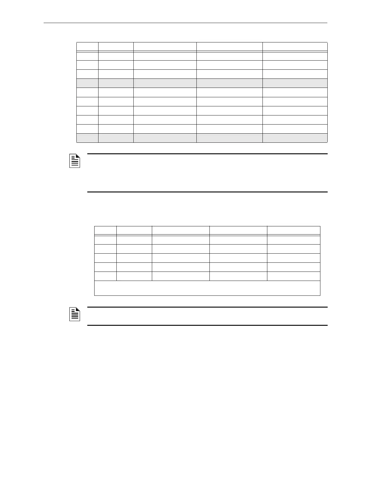
ACS Selection Group H (SLC #1, Detectors 1-64):
3 Output SLC 1, Module 131 Active SLC 1, Module 131 Trouble Controls SLC 1, Module 131
to to (see note 1) to (see note 1)
31 Output SLC 1, Module 159 Active SLC 1, Module 159 Trouble Controls SLC 1, Module 159
32 Not Used
33 Output SLC 2, Module 129 Active SLC 2, Module 129 Trouble Controls SLC 2, Module 129
34 Output SLC 2, Module 130 Active SLC 2, Module 130 Trouble Controls SLC 2, Module 130
35 Output SLC 2, Module 131 Active SLC 2, Module 131 Trouble Controls SLC 2, Module 131
to (see note 2) to (see note 2)
63 Output SLC 2, Module 159 Active SLC 2, Module 159 Trouble Controls SLC 2, Module 159
64 Not Used
NOTE:
1. Point number to Module number relationship is sequential. To determine Point to Module
relationship add 128 to Point number to arrive at Module number.
2. Point number to Module number relationship is sequential. To determine Point to Module
relationship add 96 to Point number to arrive at Module number.
Table 2.20 ACS Group G (2 of 2)
Point Type Red LED Yellow LED Switch Function
Table 2.21 ACS Group H
Point Type Red LED Yellow LED Switch Function*
1 Input Detector 001 Alarm Detector 001 Trouble Not Used
2 Input Detector 002 Alarm Detector 002 Trouble Not Used
3 Input Detector 003 Alarm Detector 003 Trouble Not Used
to to (see note) to (see note)
64 Input Detector 064 Alarm Detector 064 Trouble Not Used
* Pressing the switch button when the Switch Function is “Not Used” will cause the associated LED to
stop blinking. This is a local acknowledgement at the annunciator only: no message is sent to the panel.
NOTE: Point number to Detector number relationship is sequential; therefore, point 48 is
Detector 048.
 Loading...


