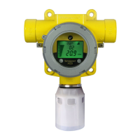
Sensepoint XCD Technical Manual SPXCDHMANEN Issue 15
20
Transmitter Wiring
Diagram 7 XCD Source 3 Wire 4-20 mA (Source)
Diagram 8 XCD Sink 3 Wire 4-20 mA (Sink)
The Sensepoint XCD transmitter may be wired in either Current SOURCE or Current SINK configuration.
These two options are offered to allow greater flexibility in the type of control system that it can be used
with. SOURCE/SINK is selectable via the switch located on the back side of the display module;
accessible by removing the display module during installation / commissioning (see chapter 9).
Note: Terminate cable screen at detector or controller, not both.
A 250 Ohm load resistor (RL) is installed in the factory; When connected to controller, this resistor should
be removed since controller has a load resistor installed internally.
CAUTION
All electrical connections should be made in accordance with any relevant local or
national legislation, standards or codes of practice.
 Loading...
