Revision 10 ST 800 SmartLine Pressure Transmitters User’s Manual Page 13
3.4.6 Flush Mounting Procedure
After the Transmitter is mounted, the Electronics Housing can be rotated to the desired
position. For insulated tanks, remove enough insulation to accommodate the mounting
sleeve and/or the flange extension.
Mount the Transmitter flanges within the limits Table 4 for the fill fluid in the capillary
tubes, with a tank at one (1) atmosphere.
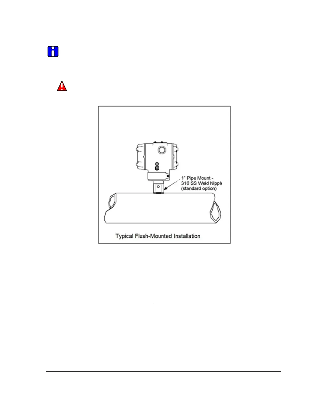
Figure 10 – Typical Flush and Flange Mounted Installations
1. Refer to Figure 10 for a representative flush-mounted Transmitter installation. Cut a hole for
a one (1) inch standard pipe in the tank or pipe at the Transmitter mounting site.
2. Weld the 1-inch mounting sleeve to the tank wall or to the hole you cut in the pipe.
3. Insert the Transmitter Meter Body into the mounting sleeve, and secure it with the locking
bolt.
4. Tighten the bolt to a torque of 4 Nm +0.3 Nm (4.7 pound-feet +0.2 pound-feet).

 Loading...


