138
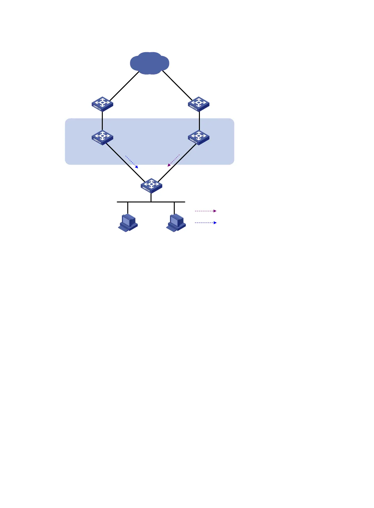
Figure 34 Network diagram
Configuration procedure
1. Create VLANs and assign ports to them. Configure the IP address of each VLAN interface as
shown in Figure 34. (Details not shown.)
2. Config
ure VRRP on Switch A:
<SwitchA> system-view
[SwitchA] interface vlan-interface 2
# Create VRRP group 1, and configure the virtual IP address 192.168.0.10 for the group.
[SwitchA-Vlan-interface2] vrrp vrid 1 virtual-ip 192.168.0.10
# Set the priority of Switch A in VRRP group 1 to 110.
[SwitchA-Vlan-interface2] vrrp vrid 1 priority 110
[SwitchA-Vlan-interface2] return
3. Configure Switch B:
# Configure the source address of BFD echo packets as 10.10.10.10.
<SwitchB> system-view
[SwitchB] bfd echo-source-ip 10.10.10.10
# Create track entry 1 to be associated with the BFD session to check whether Switch A is
reachable.
[SwitchB] track 1 bfd echo interface vlan-interface 2 remote ip 192.168.0.101 local
ip 192.168.0.102
# Create VRRP group 1, and configure the virtual IP address 192.168.0.10 for the group.
[SwitchB] interface vlan-interface 2
[SwitchB-Vlan-interface2] vrrp vrid 1 virtual-ip 192.168.0.10
# Associate VRRP group 1 with track entry 1.
Internet
Virtual router
Virtual IP address:
192.168.0.10
Vlan-int2
192.168.0.101/24
Vlan-int2
192.168.0.102/24
Switch A
Master
Switch B
Backup
L2 switch
VRRP packets
BFD probe packets

 Loading...


