152
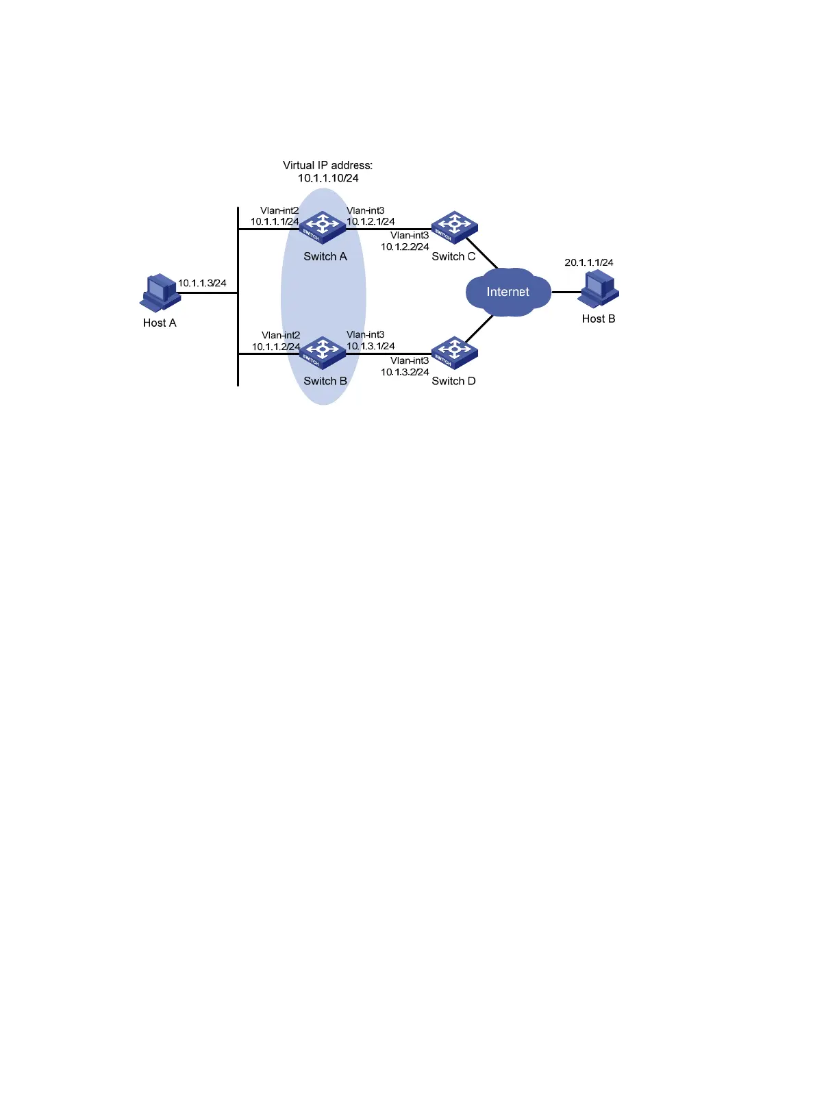
• When VRRP detects a fault on the uplink interface of Switch A through the interface management
module, Switch B forwards packets from Host A to Host B.
Figure 38 Network diagram
Configuration procedure
1. Create VLANs and assign ports to them. Configure the IP address of each VLAN interface as
shown in Figure 38. (Details not shown.)
2. Config
ure Switch A:
# Configure track entry 1 and associate it with the link status of the uplink interface VLAN-interface
3.
[SwitchA] track 1 interface vlan-interface 3
# Create VRRP group 1 and configure the virtual IP address 10.1.1.10 for the group.
[SwitchA] interface vlan-interface 2
[SwitchA-Vlan-interface2] vrrp vrid 1 virtual-ip 10.1.1.10
# Set the priority of Switch A in VRRP group 1 to 110.
[SwitchA-Vlan-interface2] vrrp vrid 1 priority 110
# Configure to monitor track entry 1, and specify the priority decrement as 30.
[SwitchA-Vlan-interface2] vrrp vrid 1 track 1 reduced 30
3. On Switch B, create VRRP group 1 and configure the virtual IP address 10.1.1.10 for the group.
<SwitchB> system-view
[SwitchB] interface vlan-interface 2
[SwitchB-Vlan-interface2] vrrp vrid 1 virtual-ip 10.1.1.10
Verifying the configuration
# Ping Host B from Host A to verify that Host B is reachable. (Details not shown.)
# Display detailed information about VRRP group 1 on Switch A.
[SwitchA-Vlan-interface2] display vrrp verbose
IPv4 Virtual Router Information:
Running Mode : Standard
Total number of virtual routers : 1
Interface Vlan-interface2
VRID : 1 Adver Timer : 100

 Loading...


