22
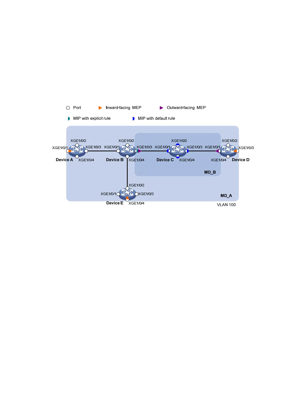
• In MD_A, Device B is designed to have MIPs when its port is configured with low level MEPs. Port
Ten-GigabitEthernet 1/0/3 is configured with MEPs of MD_B, and the MIPs of MD_A can be
configured on this port. You should configure the MIP generation rule of MD_A as explicit.
• The MIPs of MD_B are designed on Device C, and are configured on all ports. You should configure
the MIP generation rule as default.
• Use LT to identify the path between a source MEP and a target MEP or identify any link failure on
the path.
• After the status information of the entire network is obtained, use LT to detect link faults.
Figure 5 Network diagram
Configuration procedure
1. Configure a VLAN and assign ports to it:
On each device shown in Figure 5, create VLAN 100 and assign ports Ten-GigabitEthernet
1/0/1 thro
ugh Ten-GigabitEthernet 1/0/4 to VLAN 100.
2. Enable CFD:
# Enable CFD on Device A.
<DeviceA> system-view
[DeviceA] cfd enable
Enable CFD on Device B through Device E by using the same method.
3. Configure service instances:
# Create MD_A (level 5) on Device A, and create service instance 1 (in which the MA is identified
by a VLAN and serves VLAN 100).
[DeviceA] cfd md MD_A level 5
[DeviceA] cfd service-instance 1 ma-id vlan-based md MD_A vlan 100
Configure Device E as you configure Device A.
# Create MD_A (level 5) on Device B, and create service instance 1 (in which the MA is identified
by a VLAN and serves VLAN 100); in addition, create MD_B (level 3), and create service instance
2 (in which the MA is identified by a VLAN and serves VLAN 100).
[DeviceB] cfd md MD_A level 5
[DeviceB] cfd service-instance 1 ma-id vlan-based md MD_A vlan 100

 Loading...


