8.
Set the voltmeter as follows:
Range
10
V
Trigger
Ext
Delay
0
s
Coupling
DC,
1
MR
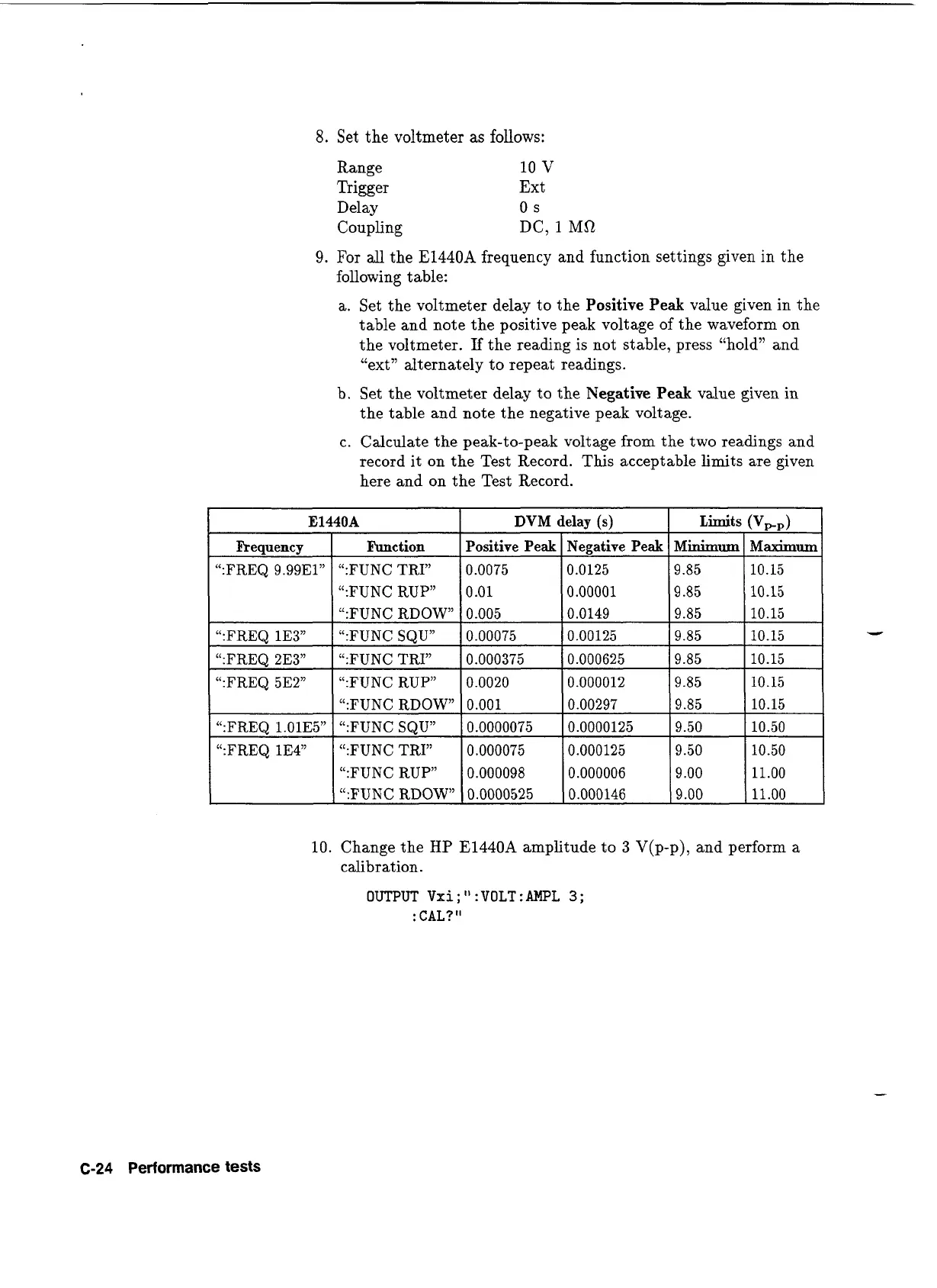
9.
For
all
the
E1440A
frequency and function settings given in the
following table:
a. Set the voltmeter delay to the
Positive Peak
value given in the
table and note the positive peak voltage of the waveform on
the voltmeter.
If
the reading is not stable, press "hold" and
"ext" alternately to repeat readings.
b. Set the voltmeter delay to the
Negative Peak
value given in
the table and note the negative peak voltage.
c. Calculate the peak-to-peak voltage from the two readings and
record it on the Test Record. This acceptable limits are given
here and on the Test Record.
":FUNC RUP"
":FUNC RDOW"
":FUNC RDOW
":FREQ
1.01E5"
":FUNC SQU"
":FREQ
1E4"
":FUNC TRI"
":FUNC RUP"
":FUNC RDOW"
DVM
delay
(s) Limits (VPp)
Positive Peak Negative Peak
Minimum
Mkum
0.0075 0.0125 9.85 10.15
0.01 0.00001 9.85 10.15
0.005 0.0149 9.85 10.15
10.
Change the
HP
E1440A
amplitude to
3
V(p-p), and perform a
calibration.
OUTPUT Vxi;":VOLT:AMPL
3;
:
CAL?
"
C-24
Performance
tests
Artisan Technology Group - Quality Instrumentation ... Guaranteed | (888) 88-SOURCE | www.artisantg.com
 Loading...


