20. For all the E1440A frequency and function settings given in the
following table:
a. Set the voltmeter delay to the
Positive Peak
value given in the
table and note the positive peak voltage of the waveform on
the voltmeter.
If
the reading
is
not stable, press "hold" and
"ext" alternately to repeat readings.
b. Set the voltmeter delay to the
Negative
Peak
value given
in
the table and note the negative peak voltage.
c. Calculate the peak-to-peak voltage from the two readings and
record it on the Test Record. This acceptable limits are given
here and on the Test Record.
E1440A
21. Switch off the high-voltage output.
OUTPUT
Vxi
;
"
:
OUTP
:
AMPL
OFF
;
Frequency
":FREQ 2E3"
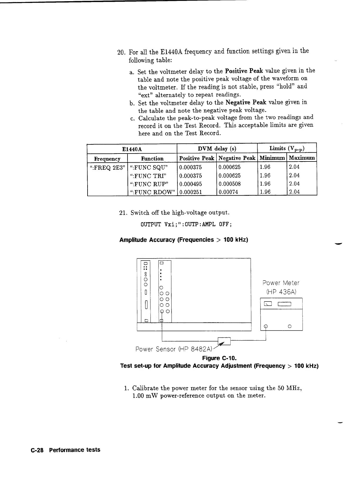
Amplitude Accuracy (Frequencies
>
100
kHz)
DVM
delay (s)
Function
":FUNC SQU"
":FUNC TRY
":FUNC RUP"
":FUNC RDOW"
Power Meter
(HP
436A)
Limits
(Vpp)
Positive Peak
0.000375
0.000375
0.000495
0.000251
L
Power Sensor
(HP
8482A)jd
Figure C-10.
Test set-up for Amplitude Accuracy Adjustment (Frequency
>
100
kHz)
Minimum
1.96
1.96
1.96
1.96
Negative Peak
0.000625
0.000625
0.000508
0.00074
1.
Calibrate the power meter for the sensor using the 50
MHz,
1.00 mW power-reference output on the meter.
Maximum
2.04
2.04
2.04
2.04
C-28
Performance tests
Artisan Technology Group - Quality Instrumentation ... Guaranteed | (888) 88-SOURCE | www.artisantg.com
 Loading...


