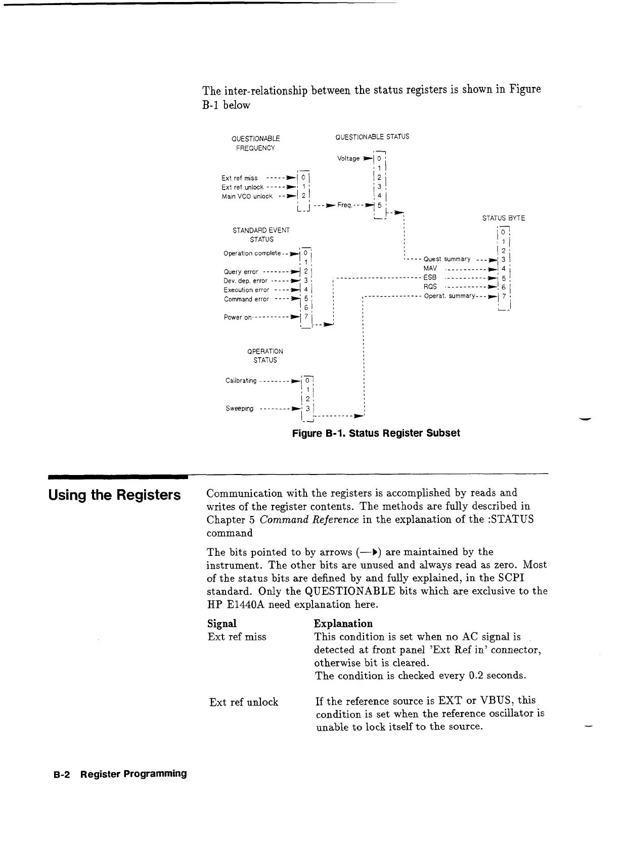
The inter-relationship between the status registers is
shown
in
Figure
B-1
below
QUESTIONABLE
FREQUENCY
Ext ref miss
------i7
Ext ref unlock
-
-
---+#
1
Ma~n VCO unlock
--*I
2
1
L-J
--
STANDARD EVENT
STATUS
'
-,
Operation complete.
-
t
0
!1!
Query error
-------4
2
/
Dev, dep. error
-
- - -
-
w
3
Execution error
-
-
- -
4
4
/
QUESTIONABLE STATUS
OPERATION
STATUS
?
STATUS BYTE
Command error
- - - -
+i:i
I
i
,
Power on.---------,
7
!
-
\--,:
Figure
B-1.
Status Register Subset
Using the Registers
Communication with the registers is accomplished by reads and
writes of the register contents. The methods are fully described in
Chapter
5
Command Reference
in the explanation of the :STATUS
command
The bits pointed to by arrows
(-b)
are maintained
by
the
instrument. The other bits are unused and always read as zero. Most
of the status bits are defined by and fully explained, in the SCPI
standard.
Only the QUESTIONABLE bits which are exclusive to the
HP
E1440A need explanation here.
Signal
Explanation
Ext ref miss This condition is set when no AC signal is
detected at front panel 'Ext Ref in7 connector,
otherwise bit is cleared.
The condition is checked every
0.2
seconds.
Ext ref unlock
If the reference source is
EXT
or VBUS, this
condition is set when the reference oscillator is
unable to lock itself to the source.
-
B-2
Register Programming
Artisan Technology Group - Quality Instrumentation ... Guaranteed | (888) 88-SOURCE | www.artisantg.com
 Loading...


