I
-
In-Channel
Frequency
Response
Test
Descrip-
tion
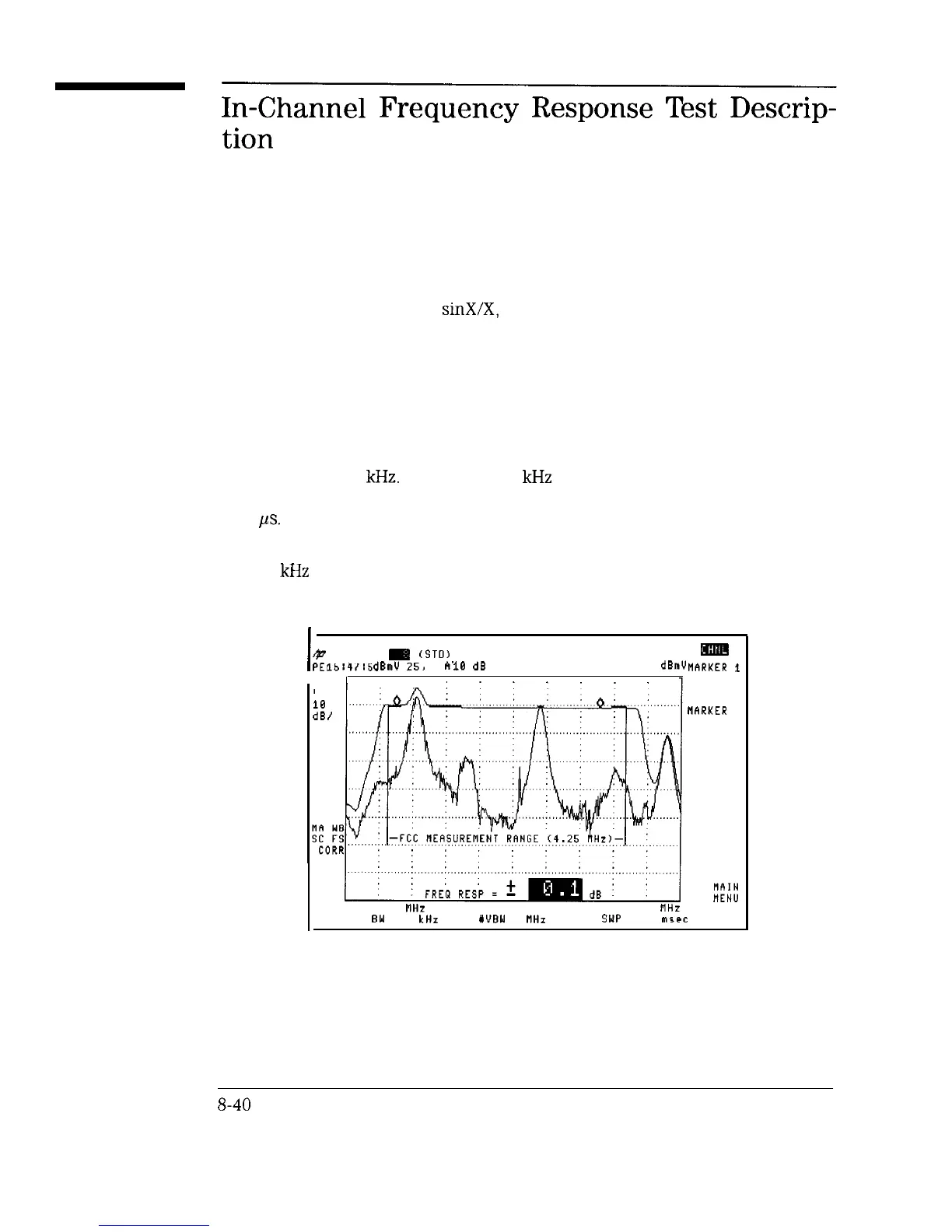
The in-channel frequency response test sets the analyzer to view full-field test
signals such as multi-burst,
sinX/X,
or line sweep. In addition, it can view
an in-channel sweep signal. The sweep signal can either be continuously
or manually swept. Figure 8-16 is the result of manually sweeping a signal
generator across the measurement range.
Multi-burst is a popular signal but it has some limitations. Figure 8-17 shows
full-field FCC multi-burst.
Note that the 0.5 MHz burst packet cannot be resolved in a resolution
bandwidth of 300
kHz.
However, 300
kHz
is the minimum bandwidth
required for the analyzer to accurately measure burst packets greater than
4.25
ps.
If all the burst packets were the same time duration, a resolution bandwidth
of 100
kHz
could be used. The burst height would not be accurate but they
all have the same relative amplitude.
I
@
CHANNEL
gS
(STO)
PEAKr
15:41:56
31.3
dBmV
JRN
25,
1995
hl
10
MKR 184.545 MHz
=
dB
20.64
dBmV,,flRKER
1
LOG
ii,
MARKER
2
RESTRRT
MAX HOLD
CALC
FRQ RESP
START 180.000
FlHz
STOP 186.000
flHz
WRES
EM
100 kHz YUBN 3 MHz
SWP 20.0 msec
T
Figure E-16. In-Channel Frequency Response
S-40