I
-
Channel Measurements
Making Channel Measurements
16:31:83
OEC 86, 1993
m
k;F
37.5 dBmU
AT
10
dB
ST0 AIR
PEAK
1
,fRF
HRCT
I
I
nenu
CENTER 57.888 MHz
SPAN
6.888
NHz
RES BW
38
kHz
UBY
38
ktlz
SWP 28.0 RI.C RT
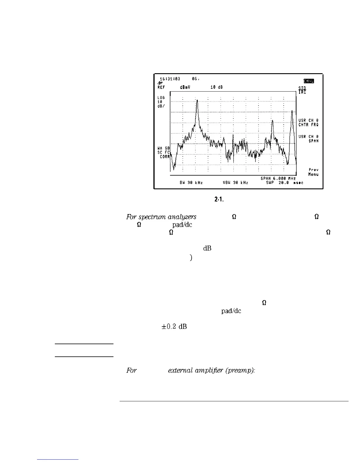
Figure
2-l.
Channel Tuning Menu
4.
Fb
spcx3rum
analgzrs with a 50
62
input: Use an external 50
62
to
75
Q
matching pad/de block to compensate for the impedance mismatch
between a 75
fl
impedance system and the spectrum analyzer’s 50
61
input
impedance. If you use an HP 11981A external pad, the external pad
causes approximately 5.8
dB
of amplitude loss. The external pad function
(EXT PAD YES MO
)
can be used to compensate for this amplitude loss.
l Connect the matching pad to the spectrum analyzer input.
l Press Analyzer Input EXT PAD YES NO to underline YES.
l Press Prev Menu to return to the Setup menu.
If you are using a spectrum analyzer with 50
fl
input impedance but are
not using an external matching pad/de block, the analyzer will compensate
for most of the impedance mismatch, but amplitude measurements can
have up to
3~0.2
dB
additional error caused by the uncompensated
mismatch over the frequency range.
CAUTION
dc voltages in excess of 25 V and ac power-line voltages in excess of
100 Vpeak can permanently damage the analyzer input.
5.
Fbr
using an
edema1
ampli$er
(preamp):
An external amplifier may be
required for the carrier-to-noise test. See Chapter 8 for more information
about when a preamplifier is required for the carrier-to-noise test. The
2-5