I
-
Channel Measurements
Making Channel
Measuremants
Carrier-to-noise test
1. Select a channel, then press Main 1 of 3 CARRIER/NOISE
2. Perform the following steps for analyzers both without and with Option
107 (when GATING is set to NO):
a. The marker defaults to the minimum system noise near the lower
channel boundary. Wait for the analyzer to return an answer.
b. To perform the carrier-to-noise test according to FCC requirements
(unless using the component summation method), remove the
modulation.
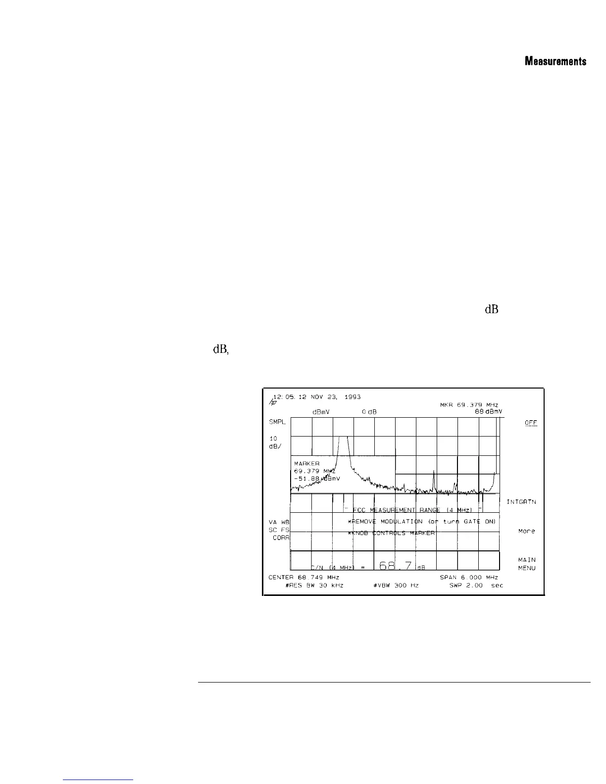
c. Using the knob, move the marker to the desired position in the
indicated FCC MEASUREMENT RANGE, see Figure 2-9.
Note that the test compares the noise level at the analyzer input to
that of the analyzer itself. If these levels are within 3
dB
of each other,
the analyzer will display the message (See MORE INFO) next to the
measurement result. See Figure 2-10. If the difference is less than 2.2
dB,
the message is in inverse video. Refer to Chapter 8 for more detailed
information about the carrier-to-noise measurement.
REF -11.5
d&n”
#AT
0
dB
-51
88
dBmV
SMPL
LOG
*
10
Ii
dB/
I
GATE
ON
E
AVERAGE
ON OFF
INTGRTN
RNG SET
Figure 2-9. Carrier-to-Noise-Modulation and Gating Off
2-15
I-