Configuring Virtual LANs (VLANs)
7 - 23
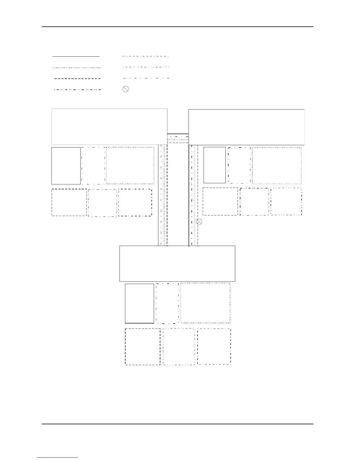
Figure 7.12 Routing between protocol-based VLANs
To configure the Layer 3 VLANs and virtual interfaces on the HP 9304M Routing Switch in Figure 7.12, use the
following procedure.
VLAN 8
= STP blocked VLAN
VLAN 7
Port 26 (tagged)
VE 6
-IP sub-net 8
-IPX network 8
VLAN 2
Ports 1 - 4
VE 1
-IP sub-net 6
VLAN 8
Ports 5 - 8
VE 2
-IPX network 6
VLAN 3
Ports 9 - 16
IP sub-net 7 (ports 9 - 12, VE 3)
IPX network 7 (ports 13 - 16, VE 4)
VE 3
-IP sub-net 7
-OSPF area 0.0.0.0
VE 4
-IPX network 7
VLAN 4
Ports 17 - 24 (untagged)
Ports 25 - 26 (tagged)
VLAN 5
Port 25 (tagged)
VE 5
-IP sub-net 4
-OSPF area 0.0.0.0
-IPX network 4
VLAN 6
Port 26 (tagged)
VE 6
-IP sub-net 5
-OSPF area 0.0.0.0
-IPX network 5
VLAN 2
Ports 1 - 4
VE 1
-IP sub-net 9
-OSPF area 0.0.0.0
VLAN 8
Ports 5 - 8
VE 2
-IPX network 9
VLAN 3
Ports 9 - 16
IP sub-net 10 (ports 9 - 12, VE 3)
IPX network 10 (ports 13 - 16, VE 4)
VE 3
-IP sub-net 10
-OSPF area 0.0.0.0
VE 4
-IPX network 10
VLAN 4
Ports 17 - 24 (untagged)
Ports 25 - 26 (tagged)
VLAN 7
Port 25 (tagged)
VE 5
-IP sub-net 8
-OSPF area 0.0.0.0
-IPX network 8
9304 B
VLAN 6
Port 26 (tagged)
VE 7
-IP sub-net 5
-OSPF 0.0.0.0
-IPX network 5
VLAN 2
Ports 1 - 4
VE 1
-IP sub-net 2
-OSPF area 0.0.0.0
VLAN 8
Ports 5 - 8
VE 2
-IPX network 2
VLAN 3
Ports 9 - 16
IP sub-net 1 (ports 9 - 12, VE 3)
IPX network 1 (ports 13 - 16, VE 4)
VE 3
-IP sub-net 1
-OSPF area 0.0.0.0
VE 4
-IPX network 1
VLAN 4
Ports 17 - 24 (untagged)
Ports 25 - 26 (tagged)
VE 5
-IP sub-net 3
-OSPF area 0.0.0.0
-IPX network 3
VLAN 5
Port 25 (tagged)
VE 6
-IP sub-net 4
-OSPF area 0.0.0.0
-IPX network 4
VLAN 6
VLAN 7
VLAN 5
VE 4, VE 7
(STP is blocking VE 4)
VLAN 2
VLAN 3
VLAN 4
VE 4, VE 5
VE 4, VE 6
9304 A
9304 C