Using Redundant Management Modules
3 - 7
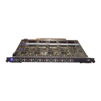
Inserting the Module
You can remove and insert modules when the system is powered on. Make sure you adhere to the cautions noted
in “Installation Precautions” on page 2-3.
1. Put on an ESD wrist strap and attach the clip end to a metal surface (such as an equipment rack) to act as
ground.
2. Remove the module or faceplate from the slot:
3. If you are replacing another module, loosen the two screws on the module you are removing.
• Pull the card ejectors towards you, away from the module front panel. The card will unseat from the
backplane.
• Pull the module out of the chassis and place in an anti-static bag for storage.
4. If you are installing a redundant management module in an unoccupied module slot, remove the blank
faceplate from the slot in which the module is to be installed. Place the blank faceplate in a safe place for
future use.
5. Remove the redundant management module from its packaging.
6. Insert the module into the chassis slot and glide the card along the card guide until the card ejectors on the
front of the module touch the chassis.
• Modules for 4-slot chassis slide in horizontally with the module label on the left.
• Modules for 8-slot chassis slide in vertically with the module label at the top.
• Modules for 15-slot chassis slide in vertically with the module label at the top.
7. Push the ejectors toward the center of the module until they are flush with the front panel of the module. The
module will be fully seated in the backplane.
8. Tighten the two screws at either end of the module.
9. If you do not use one or more of the slots, make sure that a slot faceplate is still attached over each unused
slot for safe operation and proper system cooling.
Determining Redundant Management Module Status
You can determine the status of a redundant management module in the following ways:
• Status LED – The redundant management module has two green LEDs on the right side of the CLI serial
port. The lower LED shows the management status.
• Module information in software – The module information displayed by the software indicates whether the
module is the active module, the standby module, or has another status.
Status LED
If you are located near the device, you can determine which redundant management module is currently the active
module and which one is the standby by observing the upper green LED to the right of the serial management
port. If the upper green LED is lit, the module is currently the active redundant management module. If the LED
is dark, the module is the standby. The lower green LED indicates the power status. If the lower LED is dark, the
module is not receiving power. (A module without power will not function as the active or standby module.)
Software
You can display status information for the modules using either of the following methods.
NOTE:
• Slots in a 4-slot chassis are numbered 1 – 4, from top to bottom.
• Slots in an 8-slot chassis are numbered 1 – 8, from top to bottom.