Installation and Getting Started Guide
7 - 34
interface. The IP address on each of the virtual interfaces must be in a separate sub-net. The HP device routes
Layer 3 traffic between the sub-nets using the sub-net addresses.
NOTE: Before using the method described in this section, see “Configuring VLAN Groups and Virtual Interface
Groups” on page 7-37. You might be able to achieve the results you want using the methods in that section
instead.
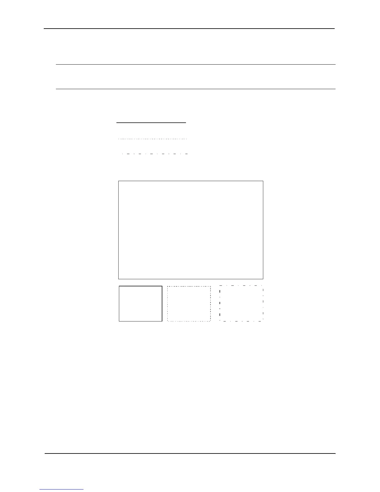
Figure 7.14 shows an example of this type of configuration.
Figure 7.14 Multiple port-based VLANs with separate protocol addresses
As shown in this example, each VLAN has a separate IP sub-net address. If you need to conserve IP sub-net
addresses, you can configure multiple VLANs with the same IP sub-net address, as shown in Figure 7.15.
VLAN 2
VE 1
-IP 10.0.0.1/24
VLAN 4
VE 3
-IP 10.0.2.1/24
VLAN 2
VLAN 3
VLAN 4
VLAN 3
VE 2
-IP 10.0.1.1/24
HP 9304M or 9308M
Routing Switch