Figure 9 8-DIMM Memory Carrier Board Slot IDs
24-DIMM Memory Carrier Load Order
The 24-DIMM memory carrier has two sides, labeled side 0 and side 1, each of which contains
a memory carrier board. The 24-DIMM memory carrier can contain up to six quads of memory.
DIMM quads are loaded in order of size from largest to smallest capacity.
DIMM quads are loaded in a certain way to balance the memory capacity between the two sides
of the memory carrier, starting with side 0. If you have more than two quads of memory to install,
load the first quad into slots 0A-0D of side 0, and load the second quad into slots 0A-0D of side
1. For the third and remaining quads of memory see “Memory Loading Rules and Guidelines”
(page 26).
The DIMM slot IDS are the same for both 24-DIMM memory carrier boards. Unique slots are
identified within the carrier by the side in which they reside. For example, slot 0A is identified as
slot 0A, side 0; or slot 0A, side 1.
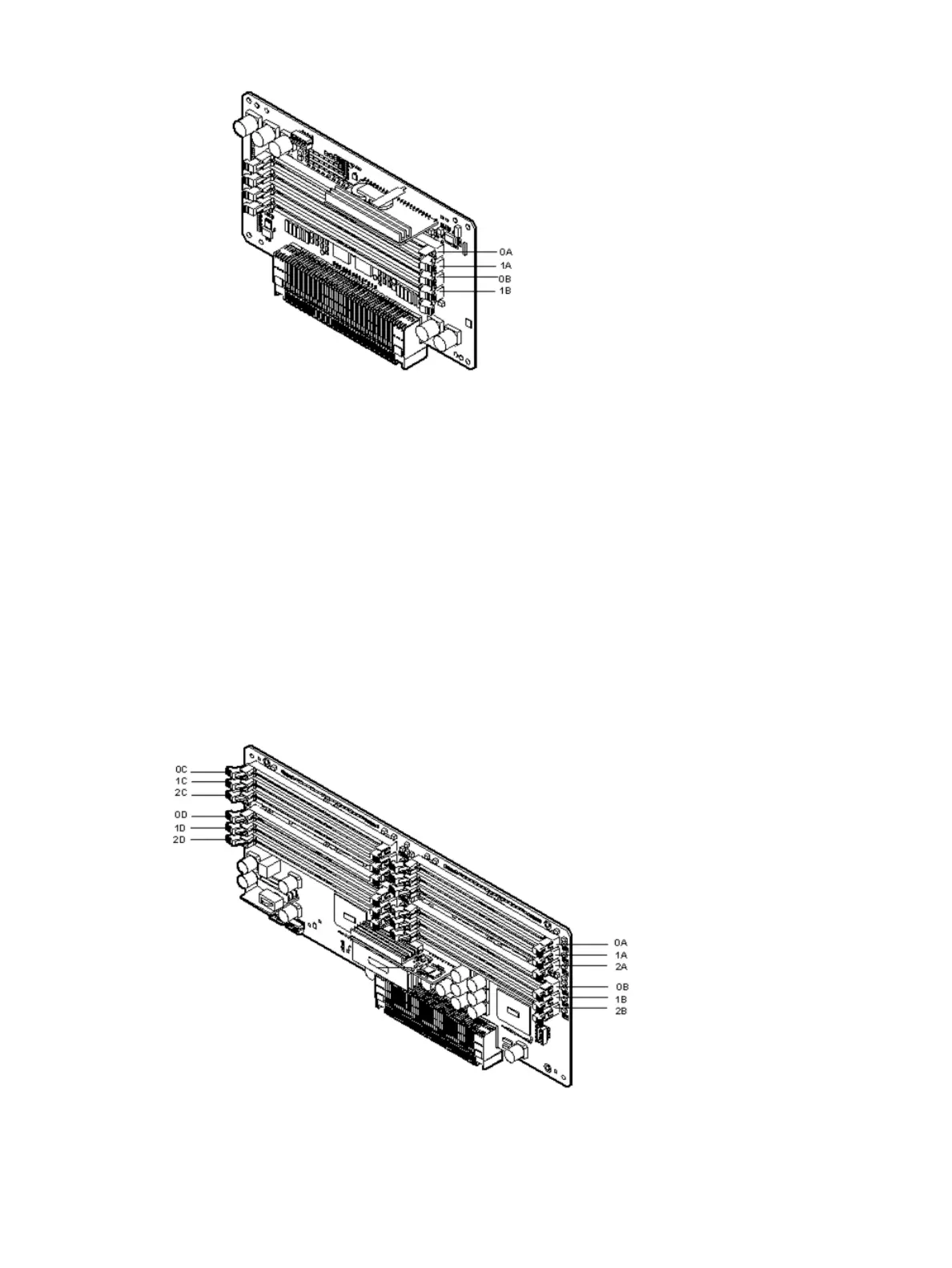
Figure 10 shows the DIMM slot IDs for the 24-DIMM memory carrier board.
Figure 10 24-DIMM Memory Carrier Board Slot IDs
Installing Additional Components 25
 Loading...


