Removal and replacement procedures 63
6.
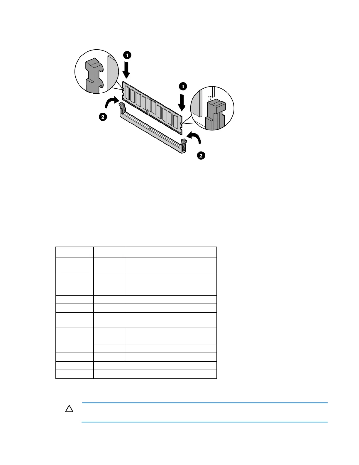
Install the DIMM.
7. Install the access panel ("Installing the access panel" on page 24).
8. Lock the tower bezel.
9. Connect each power cord to the server.
10. Connect each power cord to the power source.
11. Power up the server.
System maintenance switch
Position Default Function
1
Off Off = iLO 3 security is enabled
On = iLO 3 security is disabled
2
Off Off = System configuration can be
changed
On = System configuration is locked
3
— Reserved
4
— Reserved
5
Off Off = Power-on password is enabled
On = Power-on password is disabled
6
Off Off = No function
On = Clear NVRAM
7
— Reserved
8
— Reserved
9
— Reserved
10
— Reserved
When the system maintenance switch position 6 is set to the On position, the system is prepared to erase all
system configuration settings from both CMOS and NVRAM.
CAUTION: Clearing CMOS and/or NVRAM deletes configuration information. Be sure to
properly configure the server or data loss could occur.
 Loading...