Setting up the HPE PS1810-24G Switch (optional)
If you intend to use the server with the companion PS 1810-24G Switch, follow the procedures in this section.
For more information on switch-related settings and operational procedures, see the documentation for your
switch model on the Hewlett Packard Enterprise website.
Procedure
1. Mount the switch in a rack, on a wall, or on top of or under a horizontal surface. For detailed instructions,
see the PS1810-24G Switch Quick Setup Guide.
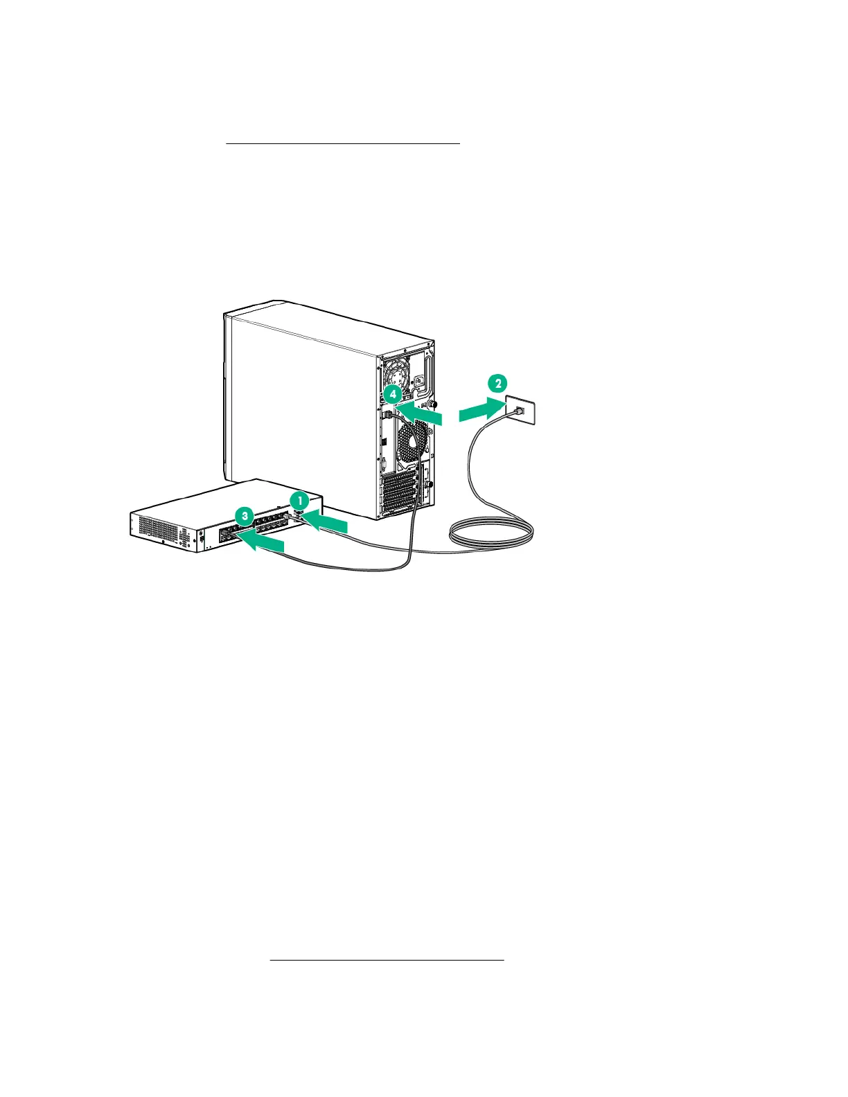
2. Connect an Ethernet cable to the switch, then connect the cable to a network jack.
3. Connect an Ethernet cable to the server NIC connector 1 or 2.
4. Connect the table to any switch network port.
5. Complete the switch Self-Test.
a. Connect the power adapter to the switch.
b. Connect the power adapter to the AC power source.
c. Check the status of the Power LED. This LE is solid green to indicate that the power connection is
established.
6. Check the status of the following switch LEDs:
a. Link/ACT LED on the switch network port that is being used - Initially, solid green to indicate successful
connection, and then flashing green to indicate active communication with the network.
b. Fault LED - Remains off to indicate successful Self-Test completion.
For more information on the location of the switch LEDs and their behavior during the Self-Test
process, see the switch documentation.
7. Complete the switch setup.
a. Ensure the NIC status LED on the server front panel is solid green.
b. Ensure the Link/Act LED on the switch's network connector is solid green to indicate successful
connection and flashing green to indicate active communication with the network.
Trusted Platform Module option
For more information about product features, specifications, options, configurations, and compatibility, see the
product QuickSpecs on the Hewlett Packard Enterprise website.
68 Setting up the HPE PS1810-24G Switch (optional)
 Loading...