Table 2-1 Robotic Total Station indicators (continued)
Indicator Description Poor (red) Fair (yellow) Excellent
(black)
Actions
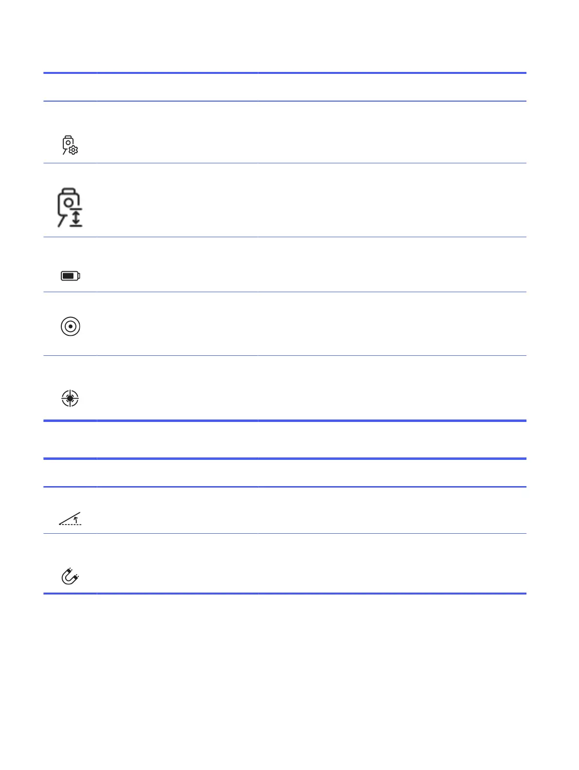
Setup
method
Indicates the setup method
used and the number of
measured points.
N/A Orientation
to line, or
resection (2
p.)
Resection (>
2 p.)
To maximize accuracy, resection setup is
recommended, as it allows for quality checks
of the measured control points. Using at
least three points enhances quality control.
RTS height Provides an estimated
elevation of the RTS above
the floor. This indicator is
shown after tracking the
robot within a 5 m² (53.8 ft²)
area on a flat surface (tilt
below 0.5°).
> 1.8 m (5.9 ft) 1–1.8 m (3.3–
5.9 ft)
< 1 m (3.3 ft) Position the RTS at the lowest feasible height
to minimize steep vertical angles during
robot prism measurements.
RTS battery
level
Indicates the current RTS
battery level.
< 5% 5–40% > 40% Internal testing suggests that RTS
performance for this application may be
compromised in low battery mode. To
achieve optimal results, avoid operating the
instrument with a low battery level.
RTS leveling Indicates the leveling status
of the RTS.
> 0.0675° 0.00567°–
0.0675°
< 0.00576° If the leveling indicator is not correct, level
the instrument using the electronic level
when possible.
Check that the tripod is in good condition or
use a tripod stabilizer if required.
Tracking
performance
Measures the dispersion of
samples received from the
RTS, to identify inaccurate
measurements.
σ > 5 mm σ 3–5 mm σ < 3 mm High dispersion in RTS measurements may
be a consequence of the poor status of
other indicators. Check the status of the
other indicators and address any issues if
possible. This should enhance the device’s
tracking performance.
Table 2-2 Ambient indicators
Indicator Description Poor (red) Fair (yellow) Excellent
(black)
Actions
Floor tilt Indicates the inclination of
the floor on which the robot
is functioning.
> 2° 1°–2° < 1° While ambient conditions cannot be altered
by the user, these indicators serve to
determine whether the robot’s operating
conditions are optimal or not.
Magnetic
interference
Indicates the level of
magnetic interference, as
determined by the measured
drift in the inertial
measurement unit.
> 1°/min 0.5–1°/min < 0.5°/min While ambient conditions cannot be altered
by the user, these indicators serve to
determine whether the robot’s operating
conditions are optimal or not.
26 Chapter 2 Product components