6.
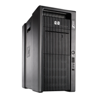
Connect the chassis power cable to the optical disk drive power cable as shown in the following
figure.
Figure 5-37 Connecting chassis power cable to optical disk drive power cable
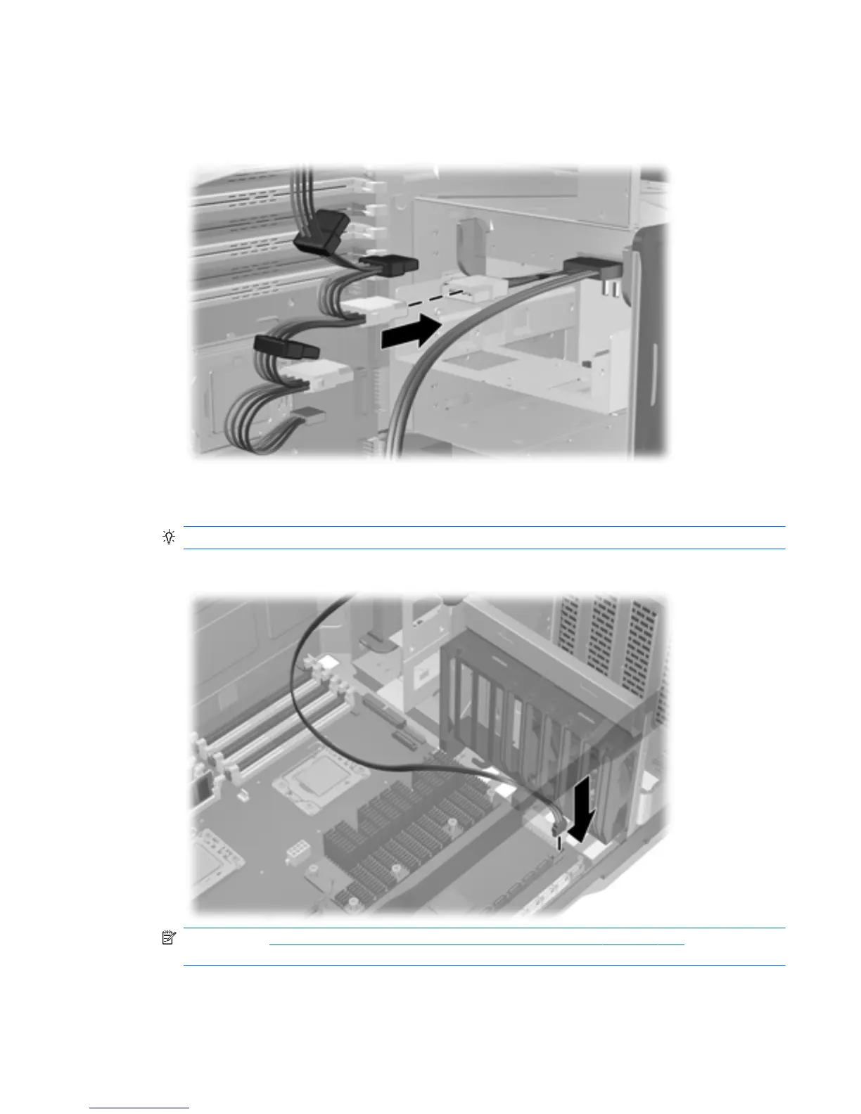
7.
Connect the optical disk drive data cable to the system board connector as shown in the following
figure.
TIP: Route the data cable along the system board.
Figure 5-38 Connecting the data cable to the system board
NOTE: See Installing a hard disk drive in the slot load optical bay on page 127 if you are
installing a hard disk drive in the slot load optical bay.
8.
Reassemble the workstation, and then replace the side access cover.
ENWW
Removing and installing components
113
 Loading...