Chapter 7 Detailed Function Introduction Shenzhen Hpmont Technology Co., Ltd.
- 54 - HD09-S Series User Manual V1.1
Ref. Code Function Description Setting Range [Default]
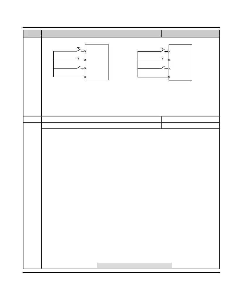
F15.16=2 F15.16=3
• SB1: Normally closed stopping button (falling
edge effective)
• SB2: Normally open FWD button (rising edge
effective)
• SB3: Normally open REV button (rising edge
effective)
• K: Direction selection terminals (PMCSx)
• K = 0 (forward) K=1 (reverse)
• SB1: Normally closed stopping button (falling
edge effective)
• SB2: Normally open running button (rising edge
effective)
F15.19 DO function 0 - 38 [2]
0: Reserved.
• So that the output terminal in a non-functional state, nor make any action.
2: The inverter is running (RUN).
• When the inverter is running, the indicator output.
3: The inverter is running FWD.
• The inverter FWD running instruction signal.
4: The inverter is running reversely.
• Inverter reverses operation indication signal.
5: DC brake.
• Inverter DC brake indication signal.
6: Zero-frequency inverter status.
• When the inverter output frequency is within zero frequency range (including stop status), it will output
indication signal.
• See parameters F15.28, F15.29.
7: Zero-frequency inverter operation.
• When the inverter output frequency is within the zero frequency range, it will output the indication
signal.
• See parameters F15.28, F15.29.
9: Frequency level detection signal (FDT).
• See parameters F15.31, F15.32.
11: Frequency arrival (FAR).
• When the output frequency of the inverter is within the positive and negative detection widths of the set
frequency, output the indication signal.
• The detection width is set by F15.27 (Frequency reach (FAR) width detection).
FWD
Three-wire
REV
SB2
SB1
SB3
DIx
DIz
DIy
GND
HD09-S
F
WD
Three-
wire
FW
D / REV
SB2
SB1
K
DIx
DIz
DIy
GND
HD09-S
 Loading...

