Shenzhen Hpmont Technology Co., Ltd Chapter 4 Electrical Installation
HD5L Series Controller User Manual ―19―
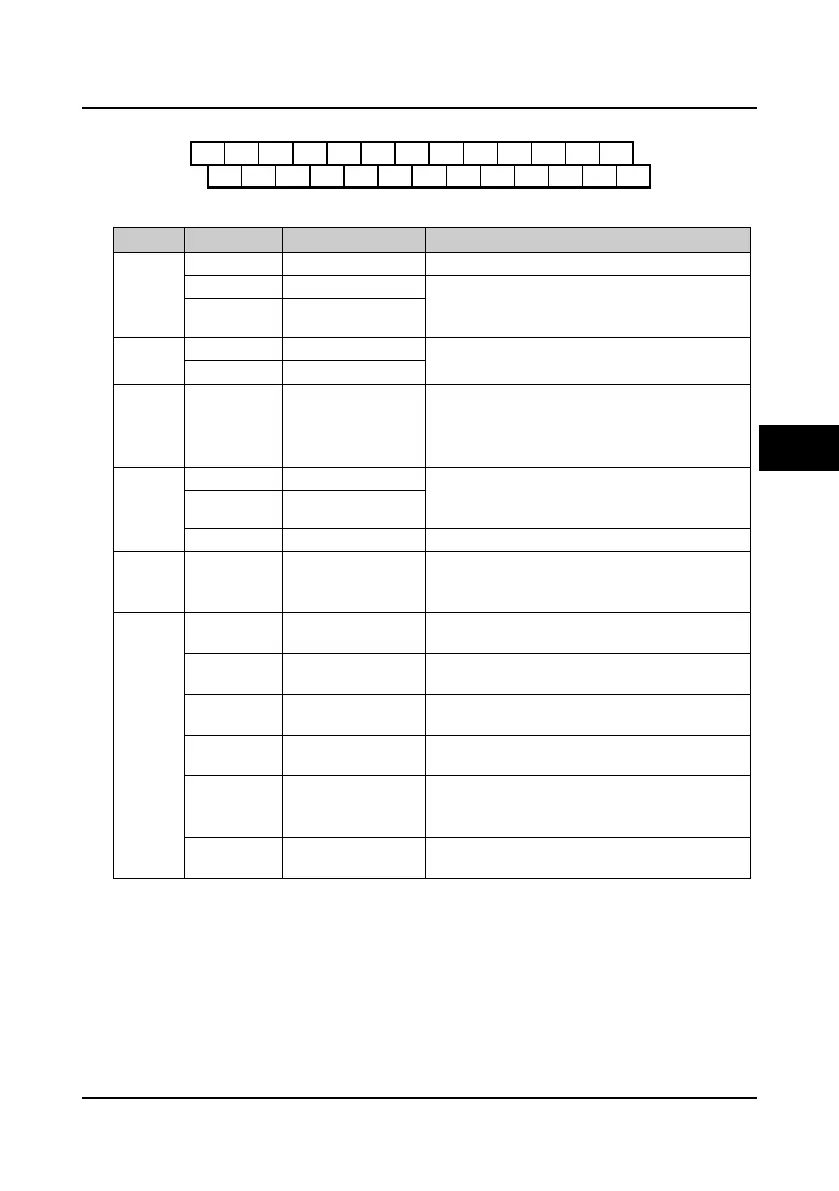
4.4.1 Control Terminal Description
Figure 4-4 Control terminal layout
Table 4-3 Control terminal function description
Item Terminal Name Function Description
Analogue
input
AI1 Anglogue input 1 Input voltage: 0-10V (input impedance: 34kΩ)
AI2 Anglogue input 2 Input voltage/current is selectable;
Input voltage: -10V-10V (input impedance: 34kΩ);
Input current: 0-20mA (input impedance: 500Ω)
AI3 Anglogue input 3
Analogue
output
AO1 Anglogue output 1
Output voltage/current signal: 0-10V/0-20mA;
Programmable output
AO2 Anglogue output 2
Digital
input
DI1-DI6 Digital input 1-6
Programmable bipolar optional input signal
Input voltage: 0-30VDC
DI1-DI5 input impedance: 4.7kΩ;
DI6 input impedance: 1.6kΩ
Digital
output
DO1 Digital output 1 Programmable optical-coupled isolation, open
collector output
Output voltage: 0-30VDC, max-output current 50mA
DO2 Digital output 2
CME DO1 reference ground Isolated from COM, default short connected COM
Relay
output
R1A/ R1B/ R1C Relay contact output
Programmable output, contact rating: 250VAC/3A or
30VDC/1A
R1B,R1C: normally closed; R1A,R1C: normally open
Power
source
+10V +10V power supply
Analogue input use +10V as reference supply,
maximum output current is 100mA
-10V -10V power supply
Analogue input use -10V as reference supply,
maximum output current is 10mA
GND
+/-10V power
reference ground
Analogue site, isolated from COM
P24 +24V power supply
Digital input use +24V as supply, maximum output
current is 200mA
SEL
Digital input common
terminal
Factory settings default SEL and P24 are connected.
Disconnected SEL and P24 when use external power
to drive DI1-DI6
COM
Digital reference
ground
Digital site, isolated from CME
+10
-10
AI1 AI2
AI3
DI1 DI2 DI3 DI4 DI5 DI6 COM R1ACOM
GND
AO1 AO2
P24 SEL DO1 R1C
GND COM CME DO2 R1B
4
 Loading...
