Shenzhen Hpmont Technology Co., Ltd Chapter 6 Function Introduction
HD5L Series Controller User Manual ―77―
6.2.14 Group F13 Analogue I/O Terminal Parameters
Code Name Description Range
factory setting
F13.00 AI1 function 0
2
0
F13.02 AI3 function 0
2
0
0: Disable.
1: Speed setting.
2: Weighing signal.
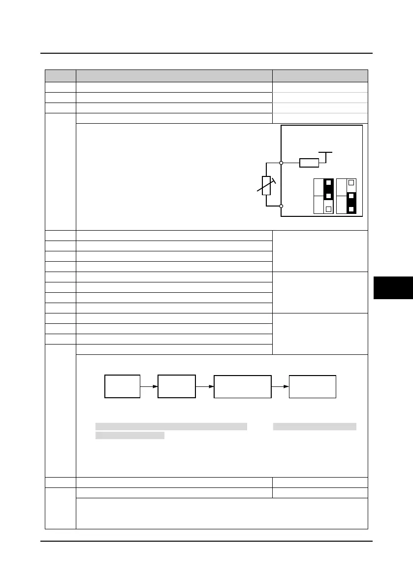
3: Motor over-heating signal input (only AI4 enabled).
• Connect the electronic thermistor embedded
motor stator coils to the controller’s analogue
input, as the right figure.
• Refer to parameters F17.01 and F17.02 about
the thermistor.
• AI1 input range: 0-10V.
• AI2-AI4 input range: -10-+10V.
-100.0
100.0
0.0%
F13.07 AI2 bias
F13.13 AI4 bias
-10.00
10.00
1.00
F13.08 AI2 gain
F13.14 AI4 gain
0.01
10.00
0.05s
F13.09 AI2 filter time
F13.15 AI4 filter time
When select AI1-AI4 as open-loop frequency setting source, the relationship between the analogue
input and the analogue value after compulting is shown as figure:
• The formula of analogue input gain and bias and analogue value is: Y=kX+b
• Here: Y is the analogue value after computing, X is the value before adjusting, k is the
analogue input gain (F13.05, F13.08, F13.11, F13.14), b is the analogue input bias (F13.04,
F13.07, F13.10, F13.13).
• F13.06, F13.09, F13.12 and F13.15 define the source filter time. It is used to filter the analogue
signal.The bigger the constant, the higher the immunity level, but the response time is prolonged
with the increase of this constant. That is, the smaller the constant, the shorter the response time,
but the lower the immunity level.
F13.16 AO1 terminal output function 0
9
0
AO2 terminal output function
0: Disable.
1: Running speed (0-max output speed).
2: Setting speed (0-max output speed).
I/O card
+5V
10k
AI4+
AI4-
CN3
1
3
CN2
1
3
V
I
V
R
Thermistor
Analogue
actual value
Analogue
input filtering
Analogue input gain
Analogue input bias
Analogue value
after computing
6
 Loading...
