Table 5-3 Mapping between the cross-sectional area of the conductor and the value of L
Cross-Sectional Area of Conductor
(mm
2
(in.
2
))
Value of L (mm(in.))
16 (0.025) 13 (0.51)
25 (0.039) 14 (0.55)
35 (0.054) 16 (0.63)
50 (0.077) 16 (0.63)
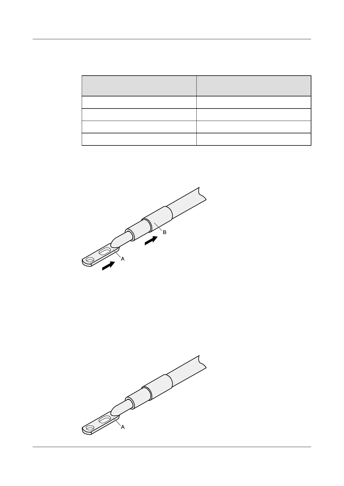
Step 2 Put the heat shrink tubing onto the bare crimping terminal, as shown in Figure 5-29.
Figure 5-29 Putting the heat shrink tubing onto the bare crimping terminal
Step 3 Put the bare crimping terminal onto the exposed conductor, and ensure that the bare crimping
terminal is in good contact with the insulation of the power cable, as shown in Figure 5-29.
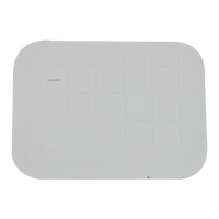
Step 4 Crimp the joint parts of the bare crimping terminal and the conductor, as shown in Figure
5-30.
Figure 5-30 Crimping the joint parts of the bare crimping terminal and the conductor (JG
terminal)
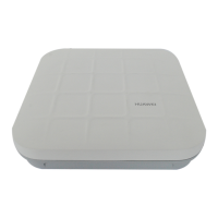
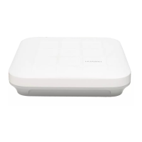
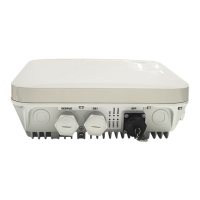
AP4050DN-E
Hardware Installation and Maintenance Guide
5 Appendix
Issue 05 (2018-02-02) Huawei Proprietary and Confidential
Copyright © Huawei Technologies Co., Ltd.
52