Table 4-11 Parallel-System Load
Item Description
N+X Parallel-System A parallel system is running. X (value range: 0–3)
indicates the number of redundant UPSs
(congurable on the LCD); N (value range: 1–4)
indicates the number of requisite UPSs (total
number of UPSs minus X). The total number of
UPSs is automatically
identied by the system.
Sys. Sout_A/Sys. Sout_ B/
Sys. Sout_C
Output apparent power of each phase in the
parallel system (Sys. Sout is displayed when
single-phase output mode is set. The parameters
are not displayed in single UPS mode.)
Sys. Pout_A/Sys. Pout_ B/
Sys. Pout_C
Output active power of each phase in the parallel
system (Sys. Pout is displayed when single-phase
output mode is set. The parameters are not
displayed in single UPS mode.)
Sys. Load ratio_A/Sys.
Load ratio_B/Sys. Load
ratio_C
Load ratio of each phase in the parallel system
(Sys. Load ratio is displayed when single-phase
output mode is set. The parameters are not
displayed in single UPS mode.)
System information is not displayed in single UPS mode.
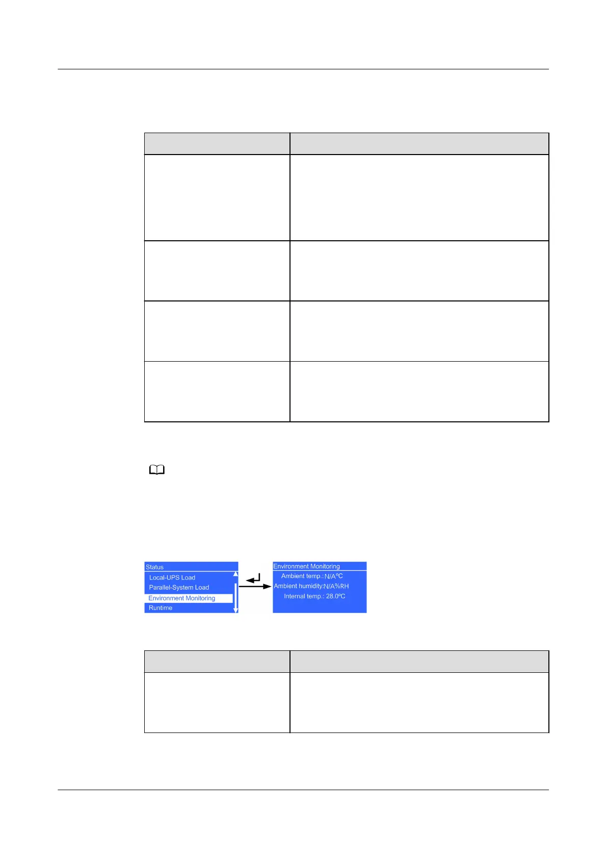
Environment Monitoring
Figure 4-16 Environment Monitoring screen
Table 4-12 Environment Monitoring
Item
Description
Ambient temp. Temperature detected by the ambient temperature
and humidity (T/H) sensor (used together with an
SNMP card; if the sensor is not connected, N/A is
displayed.)
UPS2000-G-(6 kVA-20 kVA)
User Manual 4 Control Panel
Issue 21 (2022-10-13) Copyright © Huawei Technologies Co., Ltd. 62

 Loading...