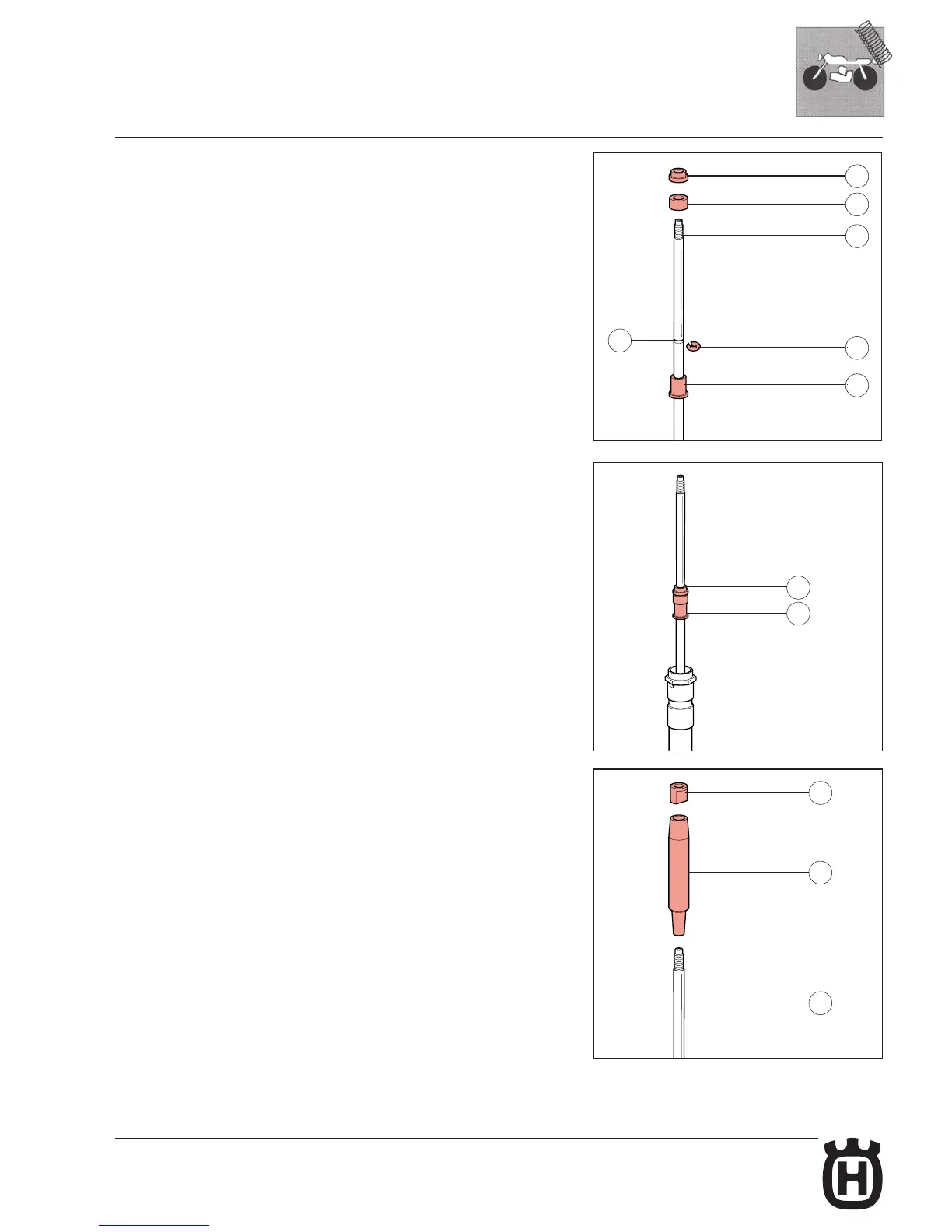
• Insert the foot buffer push rod ( 29 ) into the rod ( 32 ); this must be done in a way
that the spanner seizing side is oriented towards the
body ( 30 ) and the metal ring seat ( F ) is
exceeded.
• Insert the metal ring ( 27 ) into the proper seat( F )
• Bring the push rod ( 29 ) into contact with the stop ring.
• Insert the foot buffer ( 28 ); this must be inserted keeping the oil flow slots towards
the push rod.
• Insert the upper nut ( 26 ) and tighten it on the push rod ( 29 ).
• Hold the nut ( 26 ) with a 18 mm spanner and tighten the push rod ( 29 ) up to the
required torque (see Table 1 - Tightening Torques), using a 17 mm spanner.
• Insert the guide spring ( 24 ) in the pumping element rod ( 32 ); the guide spring
must have the smaller diameter side towards the foot buffer.
• Screw the locknut ( 23 ) till the end without tightening.