M.6 Part. N. 8000 H0368 (09-2008)
ELECTRIC SYSTEM, DIGITAL INSTRUMENT
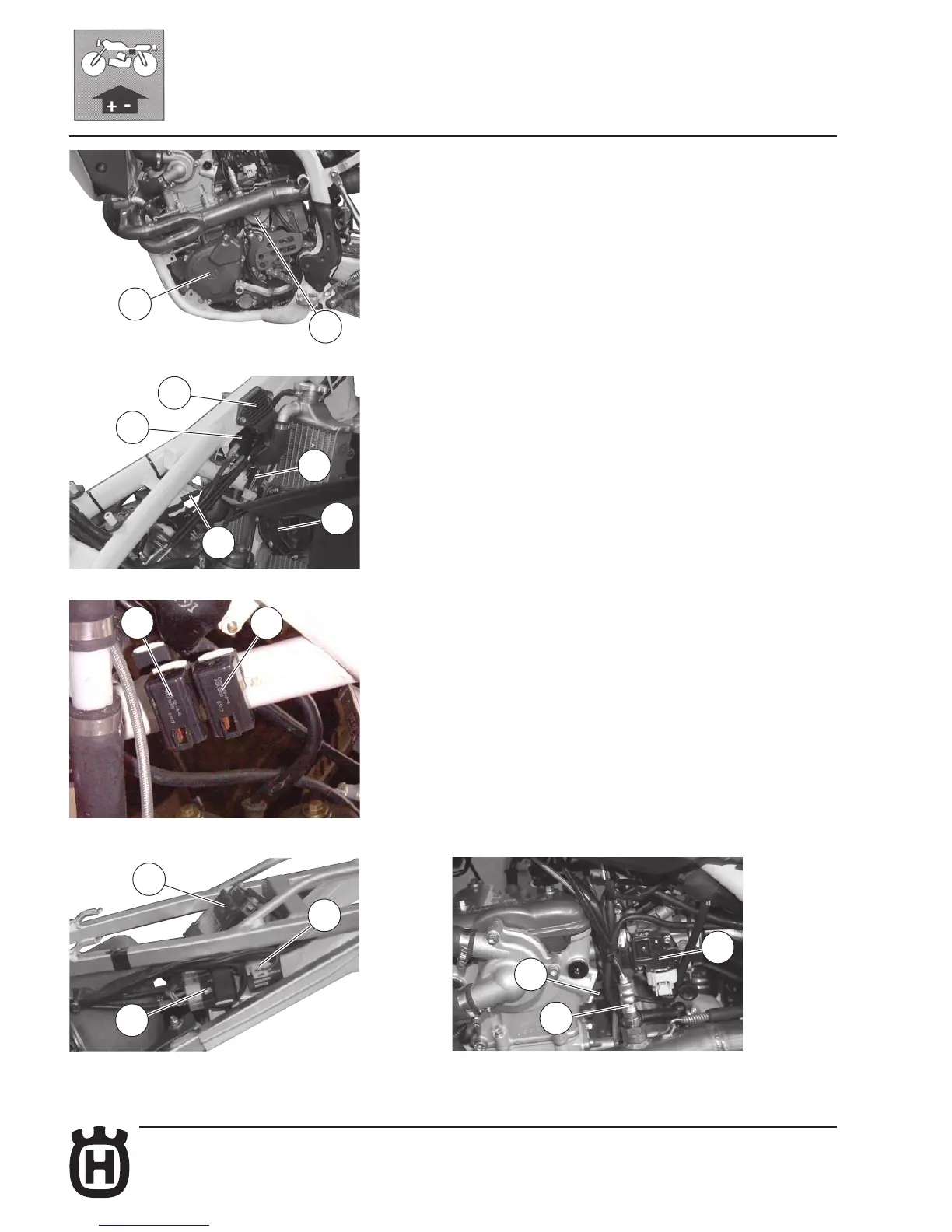
ELECTRICAL COMPONENTS LOCATION (TE-SMR)
The ignition system includes the following elements:
- Generator (1), in oil bath, on the inner side of L.H. crankcase cover;
- Electronic ignition coil (2) under the fuel tank;
- Electronic power unit C.D.I. (3) under the fuel tank;
- Voltage regulator (4) under the fuel tank;
- Spark plug (5) on the R.H. side of cylinder head;
- Starting motor 12V-450W (6) behind the cylinder;
- Electric start remote control switch (8) on the left side of the rear frame.
- M.A.Q.S. sensor (pressure, throttle control position, air temperature) (10)
on the throttle body.
The electric system includes the following elements:
- Battery 12V-6Ah (7) or, in alternative, 12V-7Ah under the saddle;
- Flashing indicator device (17) on the left side of the rear frame;
- Relay (14) for light and injection system, on the L.H. side of the frame;
- Relay (14) for the electric fan, on the R.H. side of the frame;
- Electric fan (16);
- Two fuses (9) 15A and one (13) 20A, on the right side of the rear mudguard;
- Fall sensor (11) (SMR) on the right side of the rear frame;
- Coolant temperature sensor (15);
- Lambda probe (18);
- Headlamp (20) with two filaments bulb of 12V-35/35W and parking light bulb
of 12V-3W;
- Rear tail-light (21) with stop bulbs of 12V-21W and parking light bulb of 12V 5W;
- Turn signals bulb (22) of 12V-10W;
- Fuel pump (19) inside the fuel tank.
6
1
2
4
3
16
14
8
17
10
18
15
14
14
7