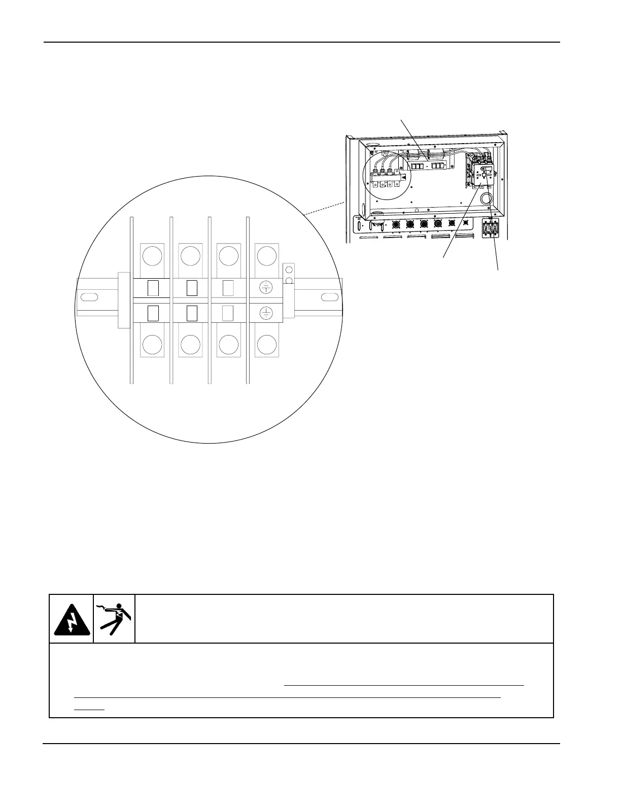
Contactor
CON1
Note: Filter on 400 VAC CE
power supplies only
Neon Light
WARNING
The neon lights attached to the contactors will turn ON as soon as the line disconnect switch
is ON. These indicators are a warning that there is line voltage at the contactors even if the
circuit breaker on the power supply is OFF. Use extreme care when measuring primary power
in these areas. Voltages present at the terminal block and contactors can cause injury or
death!
Power Measurement Location - All Voltages
5. Measure the voltage between the W, V and U terminals of TB5 located in the rear of the power supply.
See figure above. Also refer to the wiring diagram in Section 7, if required. The voltage between any 2
of the 3 terminals should be equal to the supply voltage. If there is a problem at this point, disconnect
main power and check connections, power cable, and fuses at line disconnect switch. Repair and/or
replace defective component(s) if necessary.