INSTALLATION
3-22 HT4400 Instruction Manual
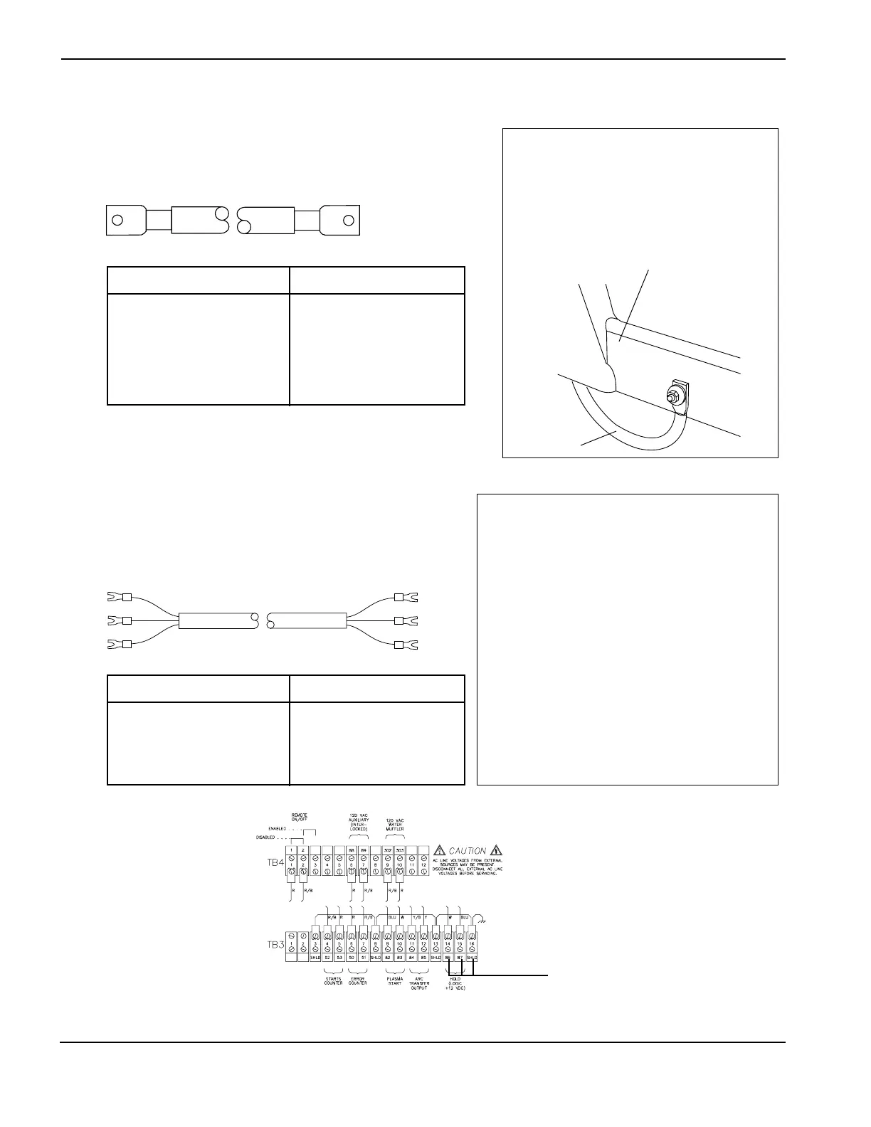
Work Table Connection
Cable - Power Supply to Work Table
Installation Notes
Pass the work cable through one of the 2"
bushings in the lower rear of the power
supply and connect to the upper bar (+) on
the center wall rear as shown on page 3-10.
Attach the other end to the work table.
Part No. Length
123418 10 ft (3 m)
023382 15 ft (4.6 m)
023136 20 ft (6.1 m)
023078 25 ft (7.6 m)
023101 30 ft (9.2 m)
023135 40 ft (12.2 m)
023079 50 ft (15.3 m)
Part No. Length
123316 60 ft (18.3 m)
023124 75 ft (22.9 m)
023080 100 ft (30.5 m)
123084 125 ft (38.1 m)
023081 150 ft (45.8 m)
123097 175 ft (53.4 m)
023188 200 ft (61 m)
Power Supply #2 Connection
Cable - Power Supply #1 to Power Supply #2
Installation Notes
When using a multi-torch system, the hold cable may be
used to interface the two power supplies. Make connec-
tions at TB3 on both supplies. TB3 is located on the
inside rear wall of the power supply. See figure below.
Note: This feature can also be directly controlled by the
CNC.
RUN LIST – Power Supply #1 to
Power Supply #2
SIGNAL PS#1 COLOR PS#2
Hold Signal 86 Black 86
Hold Common 87 Red 87
Hold Shield Gnd Shield Gnd
Part No. Length
123591 10 ft (3 m)
023340 15 ft (4.5 m)
123592 20 ft (6.1 m)
023341 25 ft (7.5 m)
123593 30 ft (9.2 m)
Part No. Length
123594 40 ft (12.2 m)
023342 50 ft (15.3 m)
023343 100 ft (30.5 m)
023344 150 ft (45.8 m)
Lower Frame of Work Table (typical)
 Loading...


