INSTALLATION
HT4400 Instruction Manual 3-21
2
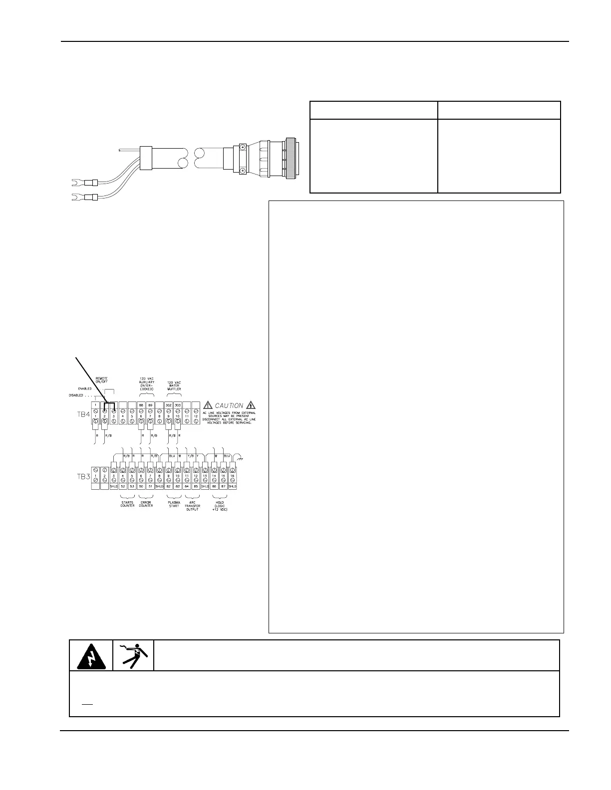
Machine Interface Connections - 2 of 2
Cable - Machine I/O Interface to
Power Supply
Installation Notes
If using the Command THC, do not connect this cable.
RUN LIST – Machine I/O Interface t
Power Supply Cable
SIGNAL Terminal COLOR 1X6
Remote OFF** 78 Green 32
Remote ON** 79 Red 37
Remote ON/OFF Shield** Cut Shield 26
Hold Signal (12VDC) Signal. Closed-ON;Open=OFF 87 White 1
Hold Common 86 Black 5
Hold Shield Cut Shield 10
Plasma Start (12VDC) Signal. Closed=Start 82 Blue 9
Plasma Start Signal 83 Black 15
Plasma Start Shield Cut Shield 14
Plasma Emergency Stop (24VAC) Signal. Closed=Stop 80 Yellow 28
Plasma Emergency Stop Signal 81 Red 33
Plasma Emergency Stop Shield Cut Shield 27
Arc Xfer Output - Signal. Dry contact relay† * 84 Red 36
Arc Transfer Output - Signal* 85 Blue 31
Arc Transfer Output - Shield* Cut Shield 25
Pierce Complete*** 135 Orange 4
Pierce Complete*** 136 Black 8
Pierce Complete Shield*** Cut Shield 13
Error Counter 167 Green 35
Error Counter 168 Black 30
Error Counter Shield Cut Shield 24
Notes:
* Contact closes after arc transfer and time delay
** To enable a remote ON/OFF switch, the jumper on TB4 must be moved from
terminals 1&2 to terminals 2&3 - see figure.
*** A contact closure will activate pierce complete and keeps shield in preflow
mode. Open the contacts for shield cutflow mode.
Note on the µP PCB that resistor R150 and capacitor C78 are connected in
series across the contacts. In some cases, one lead of R150 must be cut from
the control PC board, as the R-C circuit may provide enough current flow to
maintain machine motion input to the cutting machine.
1X6
Part No. Length
123574 10 ft (3 m)
123575 15 ft (4.6 m)
123576 20 ft (6.1 m)
023892 25 ft (7.6 m)
123577 30 ft (9.2 m)
123578 40 ft (12.2 m)
023893 50 ft (15.3 m)
Part No. Length
123579 60 ft (18.3 m)
023894 75 ft (22.9 m)
023895 100 ft (30.5 m)
123089 125 ft (38.1 m)
023896 150 ft (45.8 m)
123033 175 ft (53.4 m)
023897 200 ft (61 m)
 Loading...


