INSTALLATION
3-18 HT4400 Instruction Manual
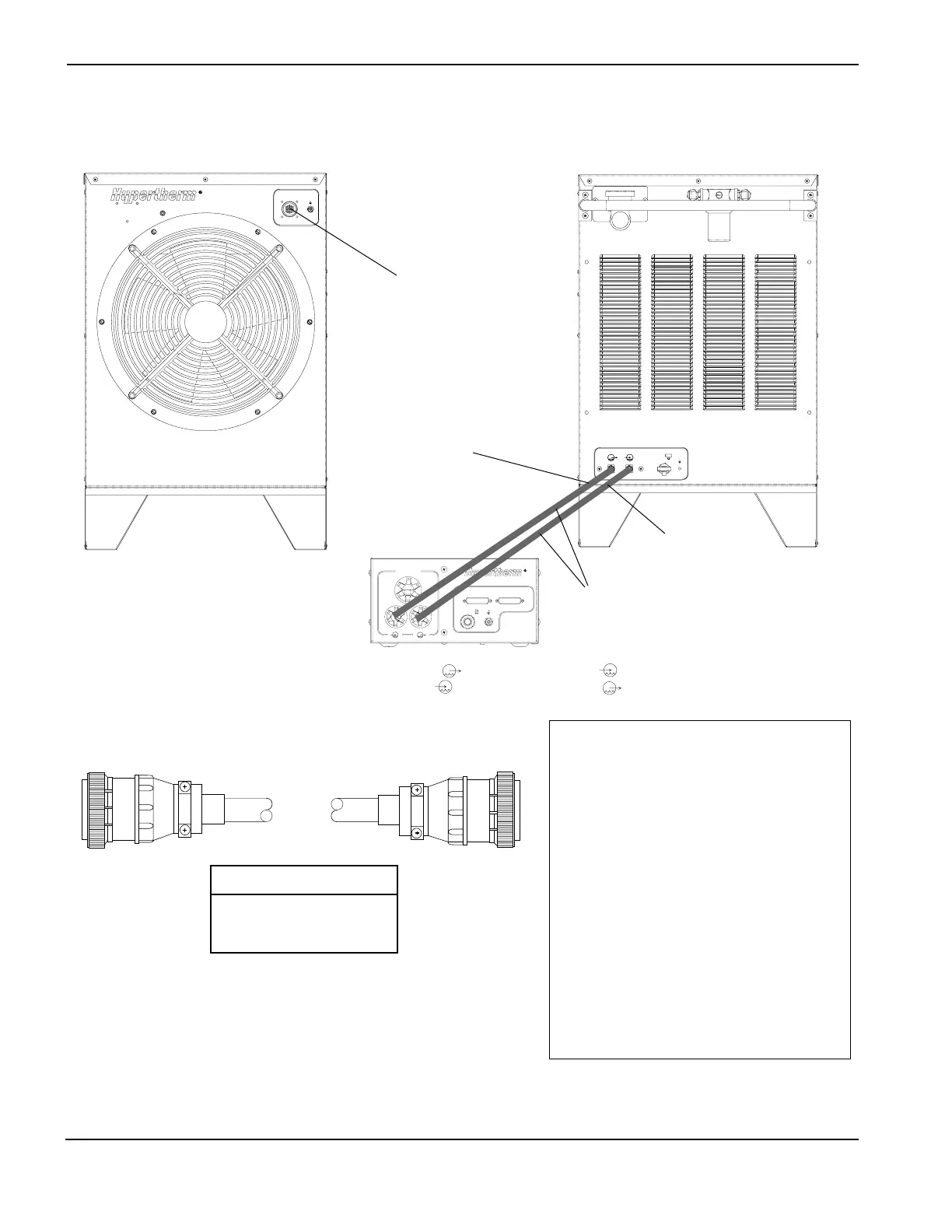
Water Cooler Connections – 1 of 2
Cable - Water Cooler to Power Supply
Installation Notes
RUN LIST – Water Cooler to
Power Supply Cable
SIGNAL 5X1 COLOR 1X5
Coolant Temp TS1 (Logic Level) 11 Black 11
Coolant Temp TS1 (Logic Level) 15 BLue 15
Shield 6 Shield 6
Flow Switch FS1 (120 VAC) 16 Yellow 16
Flow Switch FS1 (120 VAC) 12 Black 12
Shield 7 Shield 7
Water Pump (240 VAC) 17 Black 17
Water Pump (240 VAC) 18 Brown 18
Shield 19 Shield 19
Fan (120 VAC) 8 Black 8
Fan (120 VAC) 9 White 9
Shield 4 Shield 4
Solenoid V1 (120 VAC) 1 Black 1
Solenoid V1 (120 VAC) 2 Red 2
Shield 3 Shield 3
Part No. Length
123517 5 ft (1.5 m)
123518 10 ft (3 m)
123519 15 ft (4.6 m)
5X1
1X5
Ignition Console
Note:
Connect hose from Out of cooler to In of ignition console .
Connect hose from In of cooler to Out of ignition console .
See also Ignition Console connections on page 3-12.
Out
In
Out
In
Drain
Red
Green
5X1