MAINTENANCE
HT4400 Instruction Manual 5-7
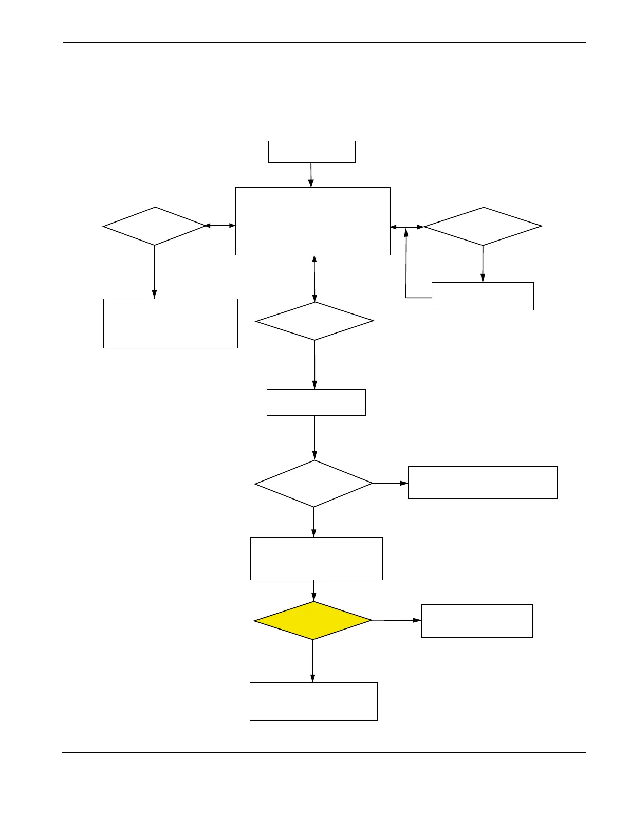
HT4400 Plasma RUN Sequence
The following flowchart shows the sequence from RUN state through the end of a cut. Shaded boxes indicate
action taken by the operator
System in RUN state
• Analog board compares output current
of each chopper to the set current
for each chopper
• Plasma START input monitored
• Phase loss monitored
• Interlocks monitored
Analog board adjusts
chopper duty cycle
Actual current too high
or too low?
START signal released?
• Plasma cut-flow OFF
• Choppers ramp down
• Choppers OFF
• Shield gases OFF
• After 100 ms, post-flow gas ON
for 10 s
• Gas console displays CA, Cb or Rd
• Error counter incremented by 1
START signal given
during post-flow?
• Post-flow stops
• START sequence begins
• Post-flow finishes its sequence
• System idle, waiting for next
START command
Ye s
Ye s
Ye s
No
Ye s
Current lost before
ramp down complete?
No
Phase loss detected?
• Main contactor CON1 OFF
• Gas console displays PL error
• All functions disabled until
plasma START signal is released
Ye s
No
No
No