HT4400 Instruction Manual e-3
3
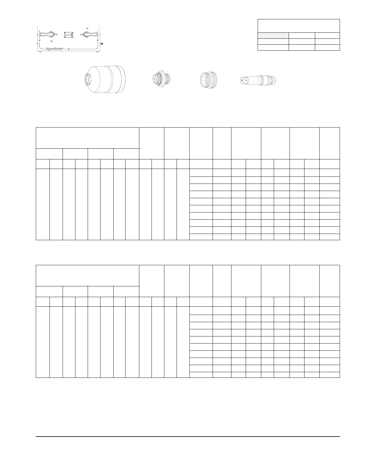
Mild Steel
O
2
Plasma / O
2
-N
2
Shield
300 Amps
Flow Rates @ 140 psi / 9.6 bar
(scfh / slh)
N
2
O
2
Preflow 194.2 / 5499 56.9 / 1611
Cutflow 173.4 / 4910 115.6 / 3273
120786
Retaining Cap
120794
Nozzle
120913
Swirl Ring
120802
Electrode
* Piercing not recommended
** Cuts on these thicknesses may result in increased cut angle variation and surface roughness. Reduce cut speed by
5%-10% for improvement with some materials.
Minimum inlet pressures remain at one setting of 140 psi (9.6 bar) for all material thicknesses.
Approximate pressures while cutting in RUN mode: PG1 72
PG2 43
1/4** 120 .062 2 190 4830 .125 3 0.3
3/8** 125 .125 3 160 4060 .250 6 0.5
1/2 130 .157 4 120 3050 .314 8 0.7
5/8 135 .188 5 100 2540 .375 10 0.9
3/4 140 .188 5 80 2030 .375 10 1.1
7/8 145 .188 5 70 1780 .375 10 1.3
1 145 .188 5 55 1400 .375 10 1.5
1-1/8 150 .188 5 50 1270 * * *
1-1/4 155 .250 6 45 1140 * * *
1-1/2 155 .250 6 35 890 * * *
ENGLISH
Material
Thickness
Plasma PlasmaShield Shield
MV1 MV2 MV3 MV4 MV5 MV6 MV7 PG1 PG2 PG1 PG2 inches Volts in. mm ipm mm/m in. mm seconds
Test
Preflow
Verify
(psi)
Test
Cutflow
Verify
(psi)
Arc
Voltage
Torch-to-Work
Distance
Cutting
Speed
Initial Pierce
Height
Pierce
Delay
Time
Test Preflow and Cutflow Adjust
(psi)
47 2 8 8 13 40 40 1747 4547
6** 120 2 .062 5108 201 3 .125 0.3
10** 125 3 .125 3871 153 6 .250 0.5
12 130 4 .157 3226 127 8 .314 0.7
15 135 5 .188 2681 106 10 .375 0.9
20 140 5 .188 1935 76 10 .375 1.1
22 145 5 .188 1796 71 10 .375 1.3
25 145 5 .188 1419 56 10 .375 1.5
30 150 5 .188 1213 48 * * *
32 155 6 .250 1134 45 * * *
35 155 6 .250 1014 40 * * *
METRIC
Material
Thickness
Plasma PlasmaShield Shield
MV1 MV2 MV3 MV4 MV5 MV6 MV7 PG1 PG2 PG1 PG2 mm Volts mm in. mm/m ipm mm in. seconds
Test
Preflow
Verify
(psi)
Test
Cutflow
Verify
(psi)
Arc
Voltage
Torch-to-Work
Distance
Cutting
Speed
Initial Pierce
Height
Pierce
Delay
Time
Test Preflow and Cutflow Adjust
(psi)
47 2 8 8 13 40 40 1747 4547
 Loading...


