Component replaCement
6-20 powermax
45
Service Manual
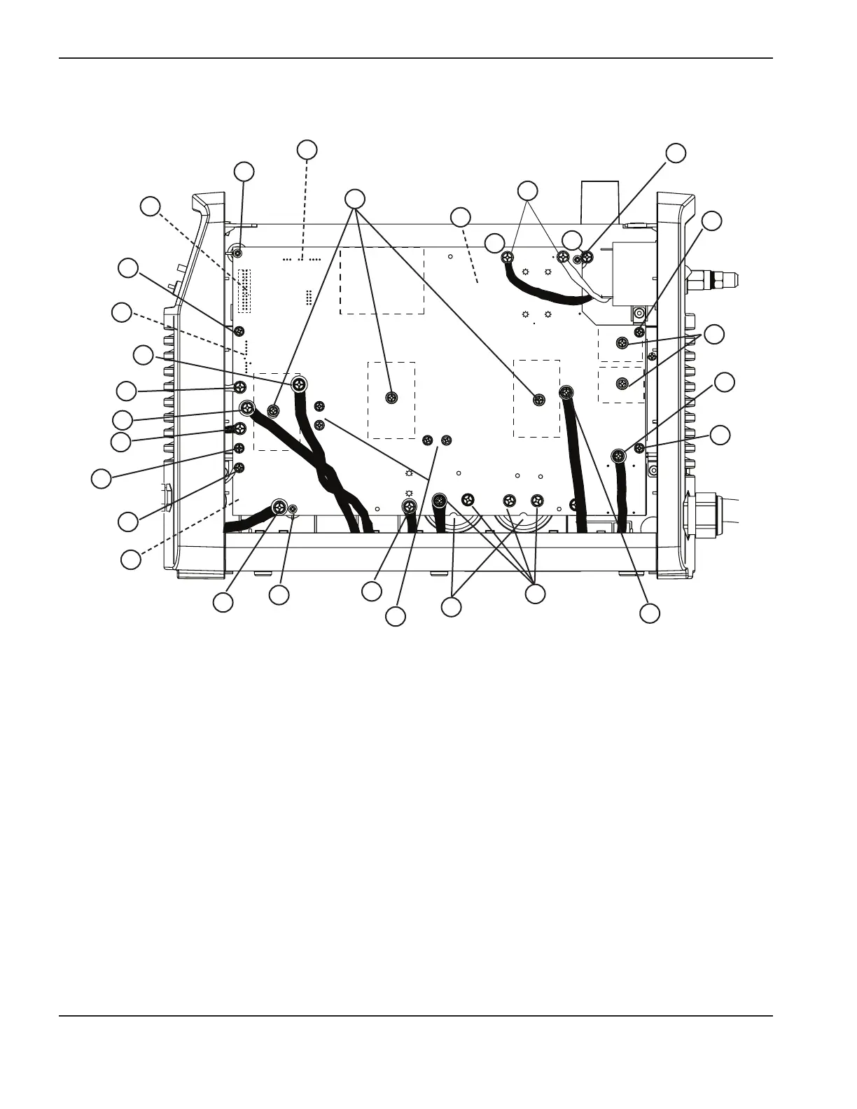
Item Description
1 Ribbon cable (J7connector)
2 Heat sink assembly screw
3 J10 and J12connectors
4 J13connector
5 J14connector
6 J16 connector
7 J17connector
8 J19connector
9 J22connector
10 Work lead connector (J21)
11 Retaining screw
12 J20connector
Item Description
13 Resistor screws (4)
14 Pressure relief vents
15 Capacitor screws (4)
16 J15connector
17 J18connector
18 Input bridge diode screws (2)
19 ON/OFF switch wires
20 J1connector
21 J2connector
22 J6connector
23 IGBT attachment screws (3)
24 J3, J4, and J5connectors
TP 19
W
-
+
-
+
TP 18
R
TP 17
B
192 VDC
192 VDC
Older 200–240V CSA and 230V CE power board
6
7
8
9
10
11
13
14
15
16
17
18
19
20
21
22
23
24
11
11