www.hysecurity.com Safety D0559 Rev. A 11
slIdedrIver slow down lImIt ramps
4"
10 cm)
Drive rail
Round-head bolts:
3/8 " (9 mm)
Must be fully
tightened and ush
before adjusting
limit switch.
Nut
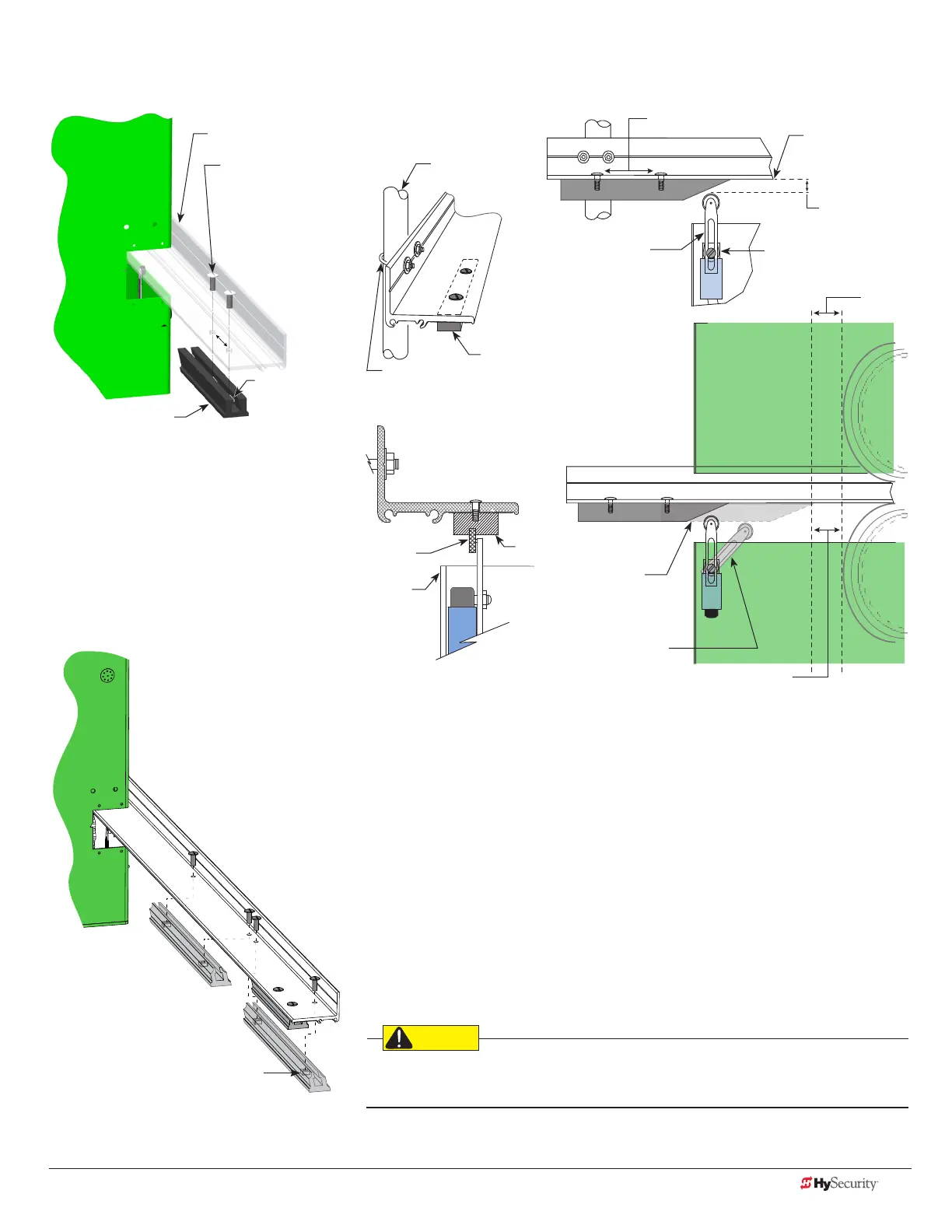
Standard Limit Ramp
The standard limit ramp is positioned
on the drive rail so it will make
contact with the limit switch and stop
approximately 2 inches (5 cm) from the
drive wheel.
Limit ramps are attached to the
underside of the drive rail when the
gate is fully open and fully closed.
SlideDriver 50VF
Slow Down Limit Ramp Kit
Nut
Two truss head screws secure each limit ramp to the drive rail. The bolts
are spaced about 4 inches (10 cm) apart.
The limit switch must be set ⅜-inch (9 mm) from the base of the drive
rail. A screw on the limit switch allows for slight adjustments in height. If
XtremeDrive wheels are used, you will need to raise the drive rail
¼ to ½ inch (3 to 13 mm) along the gate uprights and the entire
drive rail path. The limit switch placement will need to be adjusted
accordingly.
All the limit ramps are the same length.
NOTE: For a 50VF-series SlideDriver, you will need to order four (4)
Slow Down Limit Ramp Kits.
Be sure to securely fasten all limit ramps to the underside of the
drive rail when installing a 50VF-series operator.
Limit
Switch
2"
(5 cm)
4" (10 cm)
Spacing approximate
U-bolt
Support
Post
Limit Ramp
Base of Drive Rail
3/8 " (9 mm)
Height
Adjusting
Screw
Drive
Wheel
2" (5 cm)
Actuating Arm
(Tripped position)
Limit Ramp
enters chassis
cutout
Limit Ramp
Roller
Chassis
cutout

 Loading...


