86 D0559 Rev. A SlideDriver/SlideDriver 50VF Series www.hysecurity.com
meCHanICal maIntenanCe
NOTICE: Before checking the internal mechanisms of the operator, turn off all power switches.
The mechanical maintenance for the SlideDriver is not in depth or difcult, but should be performed on a
routine basis.
Schedule regular maintenance:
9 Check for signs of rust. The operator chassis is zinc plated which is corrosion-resistant, but some
environments may increase the rate of corrosion. If any areas of rust are found, reduce the spread of
corrosion by treating the areas with a rust inhibitor.
9 Grease the hydraulic cylinder every 50,000 cycles. Use NLGI #2 Grade Moly EP lithium base grease only
and apply it with a standard grease gun. Grease other bearings every 100,000 cycles.
9 Check the motor. DC motors contain carbon brushes which wear over time and must be replaced. Failure
to replace the brushes will result in damage to the DC motor. Brushes should be inspected every year in
high usage applications or every 100,000 cycles and replaced as needed.
9 Replace worn-out batteries. Refer to Clock Battery Replacement on page 85.
Drive Rail
Verify that the drive rail does not move more than 1-inch up and down or ¼-inch side-to-side throughout the
entire horizontal travel of the gate. Re-alignment is simple if the rail is mounted with U bolts. Adjusting the rail for
side-to-side movements requires inserting shims between the rail and the gate where necessary. To adjust side-
to-side movements, loosen the U bolts and add or remove shim stock. To adjust up or down, loosen the U bolts
and simply tap the rail with a hammer until the
correct height is reached.
The height of the drive rail needs to be set
between 9½ to 10 inches (24 to 25 cm) from base
of SlideDriver chassis if using XtremeDrive™
wheels. For site planning, see “SlideDriver/
SlideDriver 50VF Site Installation Overview” on
page ii.
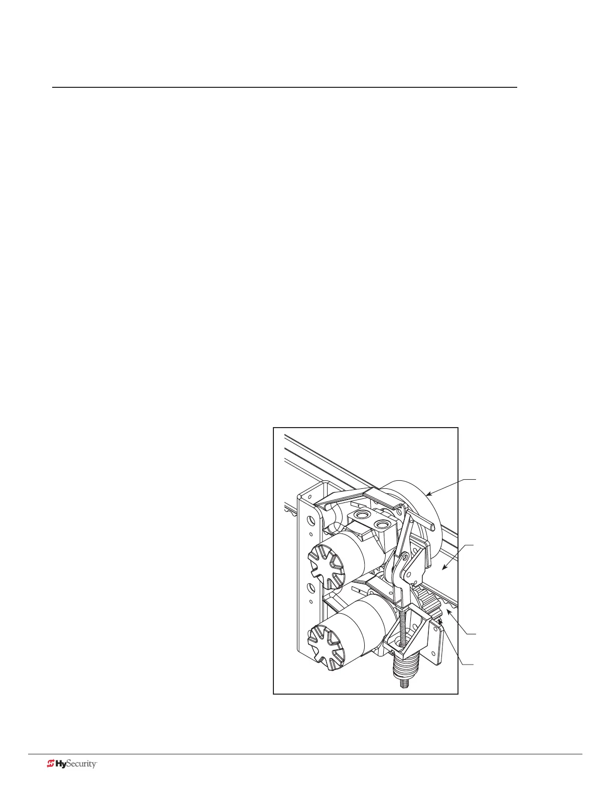
XtremeDrive™ System
AdvanceDrive™ Wheel
Drive Rail (standard)
XtremeDrive™ Wheel
Rack

 Loading...


