www.hysecurity.com Power D0559 Rev. A 21
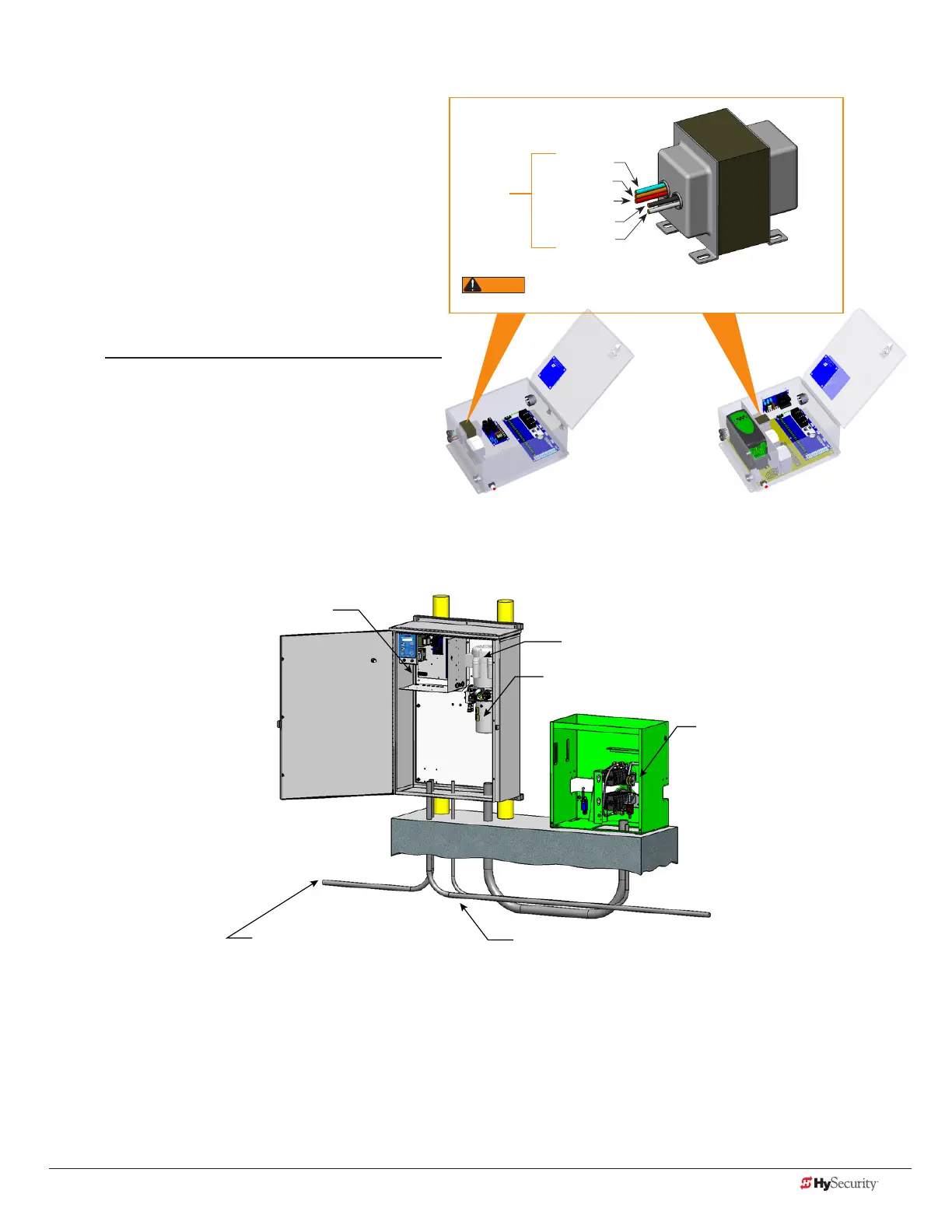
Control transformer ConneCtIons (non-ups)
Connect the AC input power to the control
transformer according to the following procedure.
1. Ensure that the primary tap on the control
transformer matches the line voltage and
frequency connected to the gate operator.
2. Measure the line voltage carefully to
distinguish between 208V and 230V branch
circuits.
NOTE: A label on the transformer top identies the
various voltage taps available.
3. Use wire nuts or crimp-connectors to
connect the power input conductors to the
applicable taps on the Control Transformer.
gate operator ConneCtIons (modular unIt)
If you have the modular unit, additional conduit is needed to house the hydraulic hoses and electrical wiring.
You need a 2-inch (5 cm) diameter conduit for hydraulic hoses and a ¾-inch (19 mm) conduit for electrical wiring.
AC input power is connected to the hydraulic pump and electrical components enclosure (HydraSupply).
A supplemental manual, provided with the product, describes the installation overview, wiring and conduit
considerations.
Control box with display
Electric motor
Hydraulic pump pack
Hydraulic motors,
Drive dheels,
Limit switches,
Toggle handle release
Vehicle detector & control
signal input wiring
High voltage electrical power
input wiring
Input taps
Blue - 480 VAC
Orange - 240 VAC
Red - 208 VAC
Black - Common
White - 120 VAC*
Control Transformer
All (Excluding SD50VF) SD50VF - series
* Variable Frequency (VF) or 2 hp gate operators:
Never connect to the white 120V wire. Make sure the
connection wires match the voltage found on the operator’s nameplate.

 Loading...


