•
For
more information on the IBM Cabling System,
see
the
IBM
Cabling System Planning and Installation
Guide,
GA27-3361, and the
IBM
Cabling System Problem Determination Guide
for
Twinaxial
Applications,
GA21-9491.
The cable signal quality check determines
if
a failure
is
present in the cable, the cable connectors, or an
attached work station. This test sends a signal down the cable, using the square wave from the B-gate output
on the oscilloscope. Signal paths up to a maximum
of
1524
meters
(5000
feet) can be checked.
It
is
normal for a surge suppressor to cause a glitch
of
the signal.
See
sample oscilloscope signals
lJand
m.
See
"712 Sample Oscilloscope Signals" on page
7-10.
Defective Cables
If
the cable
is
terminated
by
the correct load impedance, all the power
of
the transmitted signal
is
used by the
terminating impedance.
If
there
is
a cable failure that changes the impedance
of
the cable, part
of
the signal
is
returned to the signal
source as a reflection.
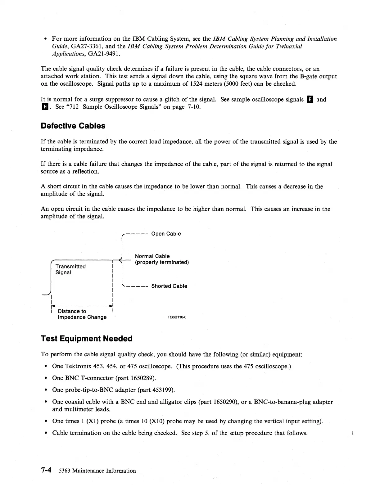
A short circuit in the cable causes the impedance to
be
lower than normal. This causes a decrease in the
amplitude
of
the signal.
An open circuit in the cable causes the impedance to be higher than normal. This causes
an
increase in the
amplitude
of
the signal.
I
I
I"
Transmitted
Signal
I
Distance to
Impedance Change
I
I
I
I
I
I
I
I
.1
,.-----
Open Cable
I
I
I
I
I
I
I
I
Normal Cable
(properly terminated)
'------
Shorted Cable
R36B116"()
Test Equipment Needed
To perform the cable signal quality check, you should have the following (or similar) equipment:
• One Tektronix 453, 454, or
475
oscilloscope. (This procedure uses the
475
oscilloscope.)
• One BNC T-connector (part
1650289).
• One probe-tip-to-BNC adapter (part 453199).
• One coaxial cable with a BNC end and alligator clips (part 1650290), or a BNC-to-banana-plug adapter
and multimeter leads.
• One times 1 (Xl) probe (a times
10
(XIO)
probe may
be
used
by
changing the vertical input setting).
• Cable termination on the cable being checked.
See
step
5.
of
the setup procedure that follows.
7-4
5363
Maintenance Information
 Loading...