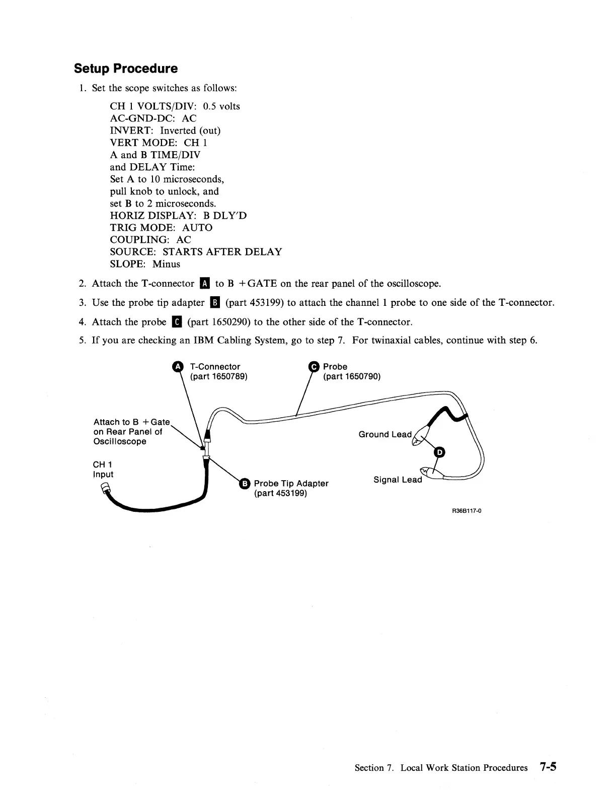
Setup Procedure
1.
Set the scope switches as follows:
CH
1 VOLTS/DIV: 0.5 volts
AC-GND-DC: AC
INVERT: Inverted (out)
VERT
MODE:
CH
1
A and B TIME/DIV
and
DELAY
Time:
Set A to
10
microseconds,
pull knob to unlock, and
set B to 2 microseconds.
HORIZ
DISPLAY: B
DL
Y'D
TRIG
MODE: AUTO
COUPLING:
AC
SOURCE: STARTS
AFTER
DELAY
SLOPE: Minus
2.
Attach the T -connector
II
to B +
GATE
on the rear panel
of
the oscilloscope.
3.
Use the probe tip adapter
II
(part 453199) to attach the
channell
probe to one side
of
the T-connector.
4.
Attach the probe
II
(part 1650290) to the other side
of
the T-connector.
5.
If
you are checking
an
IBM Cabling System, go to step
7.
For
twinaxial cables, continue with step
6.
Attach
to
B + Gate
on
Rear
Panel
of
Oscilloscope
CH
1
Input
T-Connector
(part
1650789)
Probe
(part
1650790)
Probe
Tip
Adapter
(part
453199)
Ground
Lead
R36B117·0
Section
7.
Local Work Station Procedures 7-5
 Loading...