EasyManuals Logo

IBM System x3100 M4 Problem Determination And Service Guide

IBM System x3100 M4
332 pages
To Next Page IconTo Next Page
To Previous Page IconTo Previous Page
Page #241 background imageLoading...
Page #241 background image
5. Connect the hard disk drive power cables to the backplate (connector P3 to
bay 3, connector P4 to bay 4, connector P5 to bay 5, and connector P6 to bay
6,).
6. Connect the hard disk drive signal cables to the SATA connectors on the
backplate (connector 0 to bay 3, connector 1 to bay 4, connector 2 to bay 5,
and connector 3 to bay 6,)
7. Connect the hard disk drive signal cables to the SATA connectors on the
system board or the connector on the adapter (if one is installed).
Note: In the LSI RAID utility, SATA 1 represents hard disk drive in drive bay
two and SATA 2 represents hard disk drive in drive bay one (see “Installing a
simple-swap hard disk drive” on page 196).
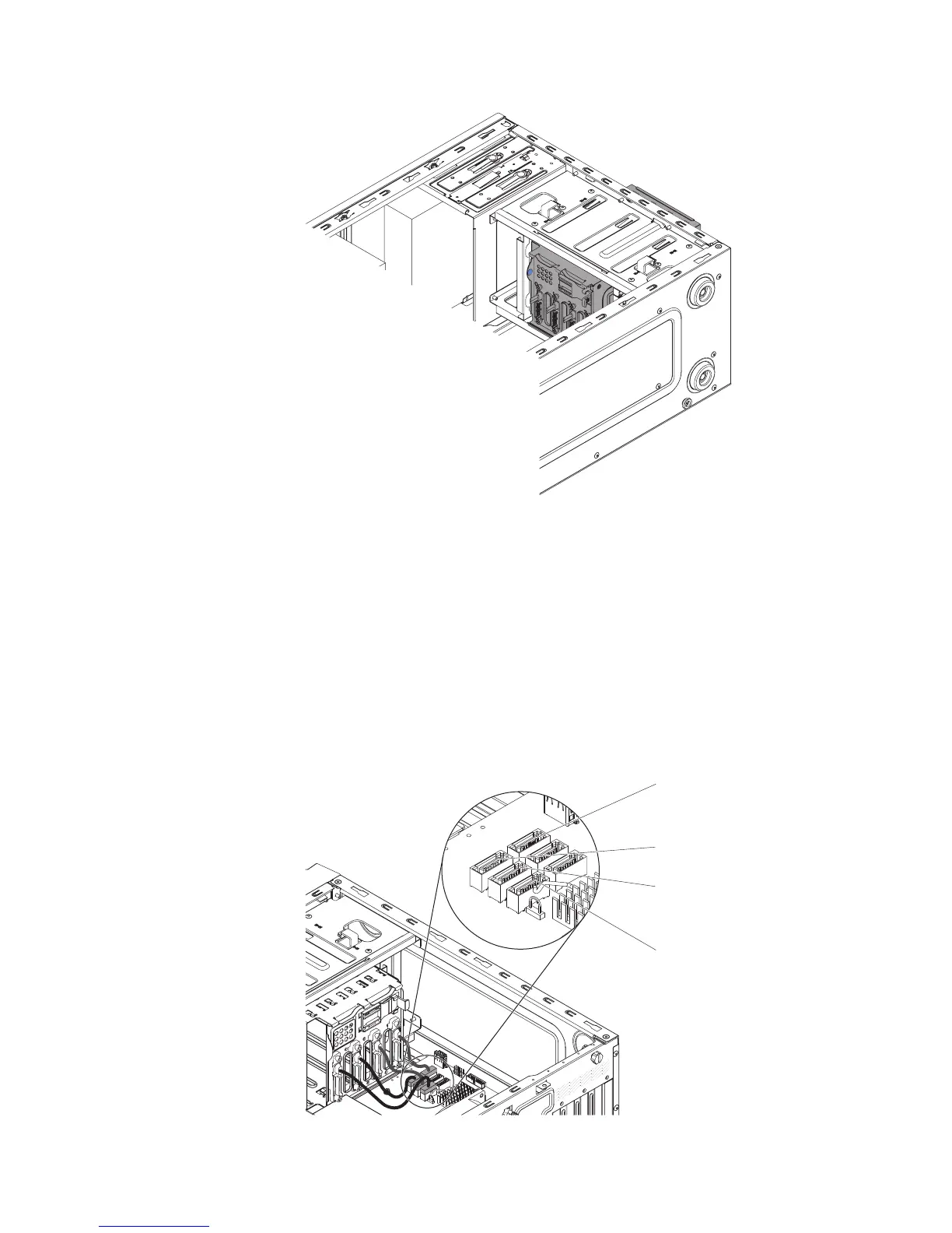
The following illustrations shows the SATA connectors on the system board:
HDD 0 - SATA 0
HDD 1 - SATA 2
HDD 2 - SATA 1
HDD 3 - SATA 3
8. Secure the cables with the retention clips.
Chapter 5. Removing and replacing server components 221

Table of Contents

Other manuals for IBM System x3100 M4

Questions and Answers:

Question and Answer IconNeed help?

Do you have a question about the IBM System x3100 M4 and is the answer not in the manual?

IBM System x3100 M4 Specifications

General IconGeneral
MemoryUp to 32 GB DDR3 ECC UDIMM
Memory Slots4 DIMM slots
Form FactorTower
ChipsetIntel C202
Processor Sockets1
ProcessorIntel Xeon E3-1200 v2 series, Intel Pentium series, Intel Celeron series
StorageUp to 4x 3.5-inch
Power Supply350W
Hard Drive Bays4 x 3.5"
RAID SupportRAID 0, 1, 10
Network InterfaceGigabit Ethernet
Expansion Slots1 x PCIe 3.0 x16, 1 x PCIe 2.0 x4
Operating System SupportWindows Server, Red Hat Enterprise Linux, SUSE Linux Enterprise Server

Related product manuals