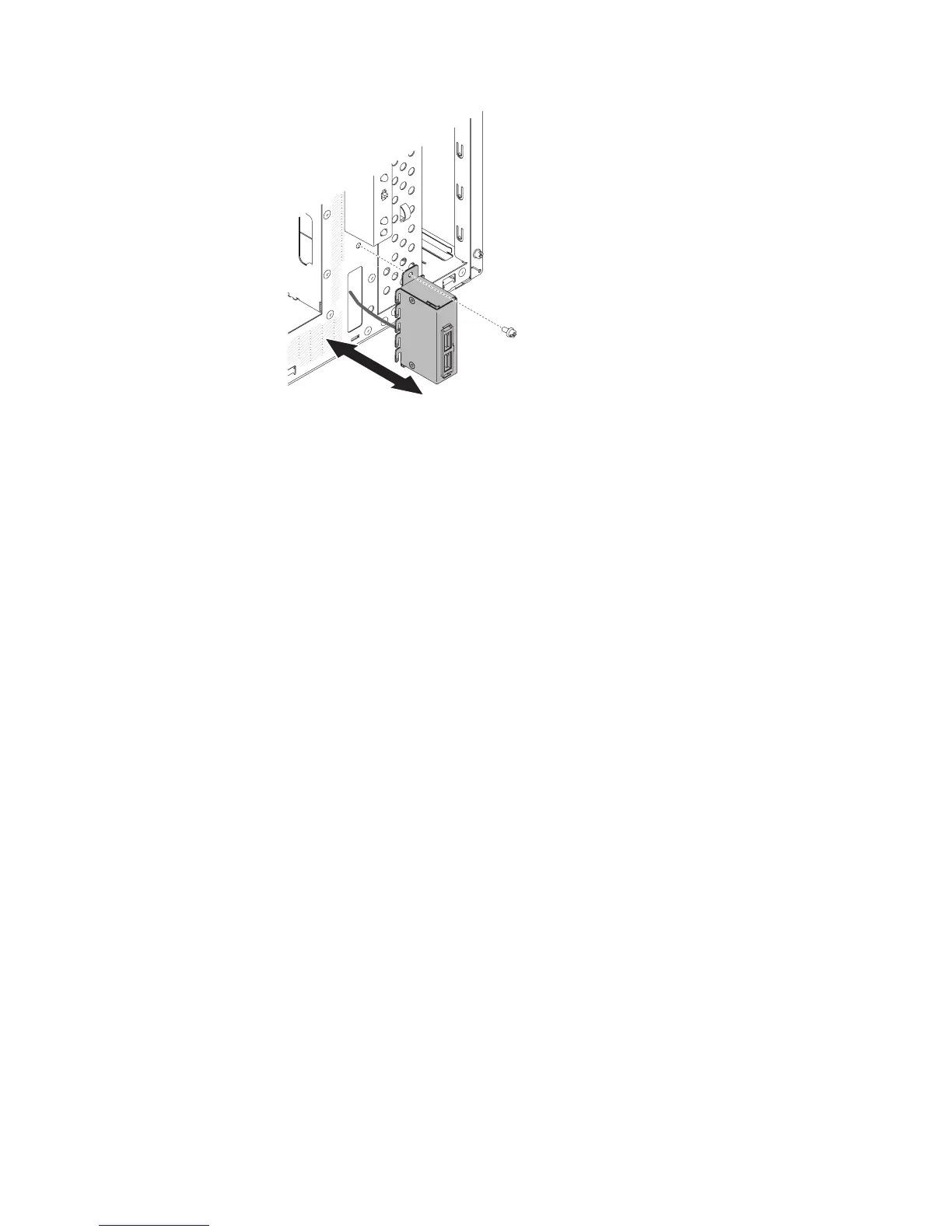
8. Place the tab on the bottom edge of the USB housing into the bottom of the
opening in the chassis.
9. Tilt the top of the USB housing into position to the end.
10. Secure the front USB housing with the screw.
11. Reroute and connect the front USB cable to the front USB connector on the
system board (see “System-board internal connectors” on page 17 for the
location of the front USB connector).
12. Install the air duct.
13. Install the side cover (see “Installing the side cover” on page 167).
14. Stand the server back up in its vertical position.
15. Install bezel (see “Installing the bezel” on page 171).
16. Reconnect the external cables and power cords; then, turn on the attached
devices and turn on the server.
To install the front USB connector assembly on the 5U server model with hot-swap
power supplies (Model name: 2582-F4x), complete the following steps. For 4U
server models with non-hot-swap power supplies, please see the above
sub-section.
1. Read the safety information that begins on page vii and “Installation guidelines”
on page 163.
2. Turn off the server and all attached devices; then, disconnect all power cords
and external cables.
3. Unlock and remove the side cover (see “Removing the side cover” on page
166).
4. Remove the lower bezel (see “Removing the lower bezel” on page 171).
5. Remove the upper bezel (see “Removing the upper bezel” on page 174).
6. Carefully insert the front USB cable through the opening in the front of the
chassis.
7. Squeeze the spring clips on the sides of the front USB connector assembly
and insert the assembly into the housing through the back of the housing.
234 IBM System x3100 M4 Type 2582: Problem Determination and Service Guide

 Loading...


