If an error occurs, view the light path diagnostics LEDs in the following order:
1. Check the operator information panel on the front of the server.
v If the information LED is lit, it indicates that there is a suboptimal condition
in the server.
v If the system-error LED is lit, it indicates that an error has occurred.
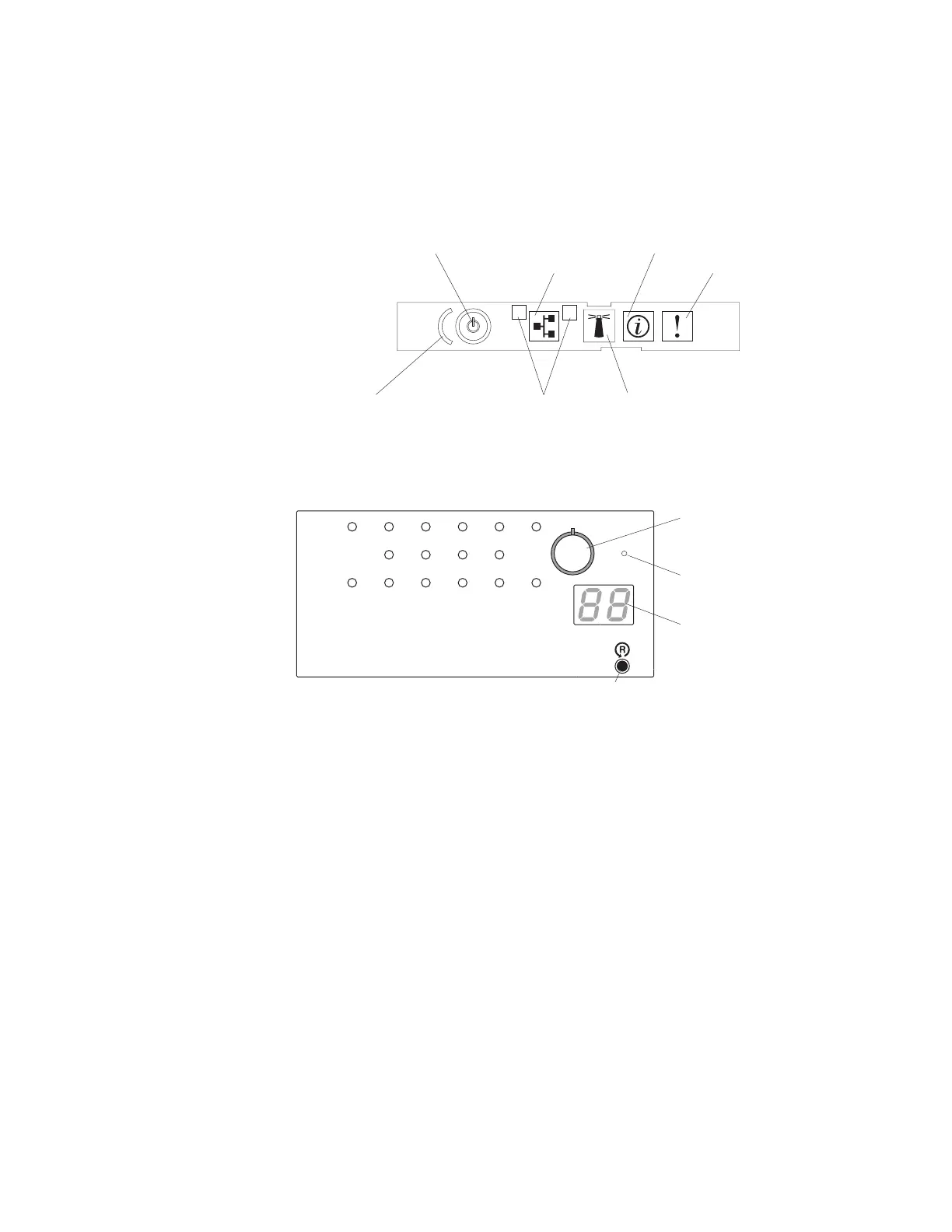
The following illustration shows the operator information panel.
Information LED
System-error LED
1
2
Ethernet icon LED
Power-control button/power-on LED
Ethernet port activity LEDs
Locator button/locator LED
Power-control button cover
2. To view the light path diagnostics panel, press the release latch on the front of
the operator information panel to the left; then, slide it forward. This reveals
the light path diagnostics panel. Lit LEDs on this panel indicate the type of
error that has occurred.
DASD
NMI
PCIPS SP
CNFG
MEM
CPU
FAN
VRM
OVER SPEC
TEMP
Light Path Diagnostics
BRD
LOG
LINK
RAID
REMIND
NMI button
Reset button
Remind
button
Check point
code display
Note: (Trained service technician only) The NMI button is used for
operating-system debugging purposes and will cause the server to reset if it is
pressed.
Look at the system service label on the top of the server, which gives an
overview of internal components that correspond to the LEDs on the light path
diagnostics panel. This information and the information in “Light path
diagnostics LEDs” on page 63 can often provide enough information to correct
the error.
3. Remove the server cover and look inside the server for lit LEDs. Certain
components inside the server have LEDs that will be lit to indicate the location
of a problem. For example, a microprocessor error will light the LED next to
the failing microprocessor on the microprocessor board.
Chapter 3. Diagnostics 59
 Loading...


