Memory expansion module indicators, LEDs, and power
This topic discusses memory expansion module indicators, LEDs, and power.
This section describes the indicators and light-emitting diodes (LEDs) on the front
and rear of the IBM MAX5 for System x memory expansion module.
Front view
This topic provides an illustration that shows the indicators on the front of the
memory expansion module.
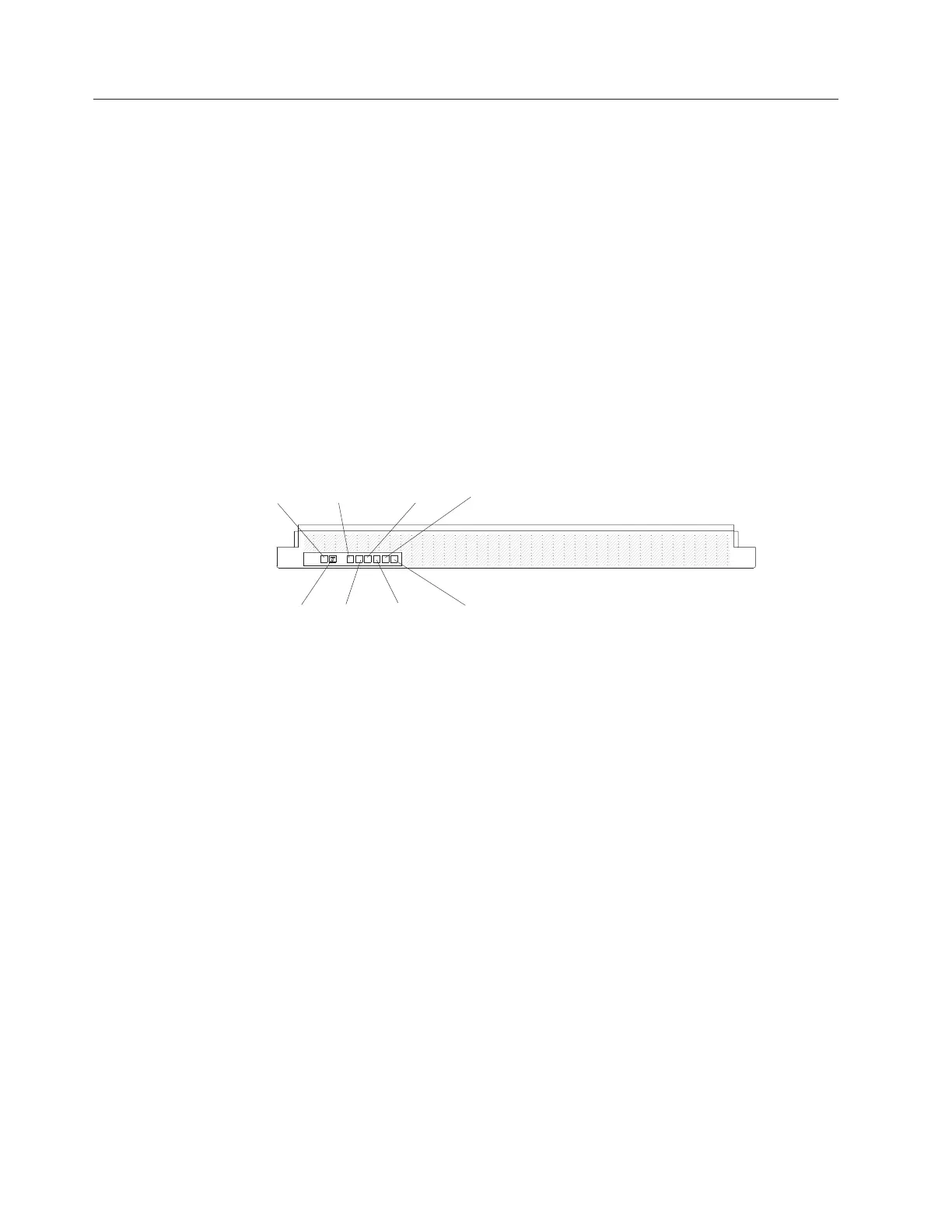
The following illustration shows the indicators on the front of the memory
expansion module. All of the LEDs are controlled by the server integrated
management module (IMM).
Note: The memory expansion module does not have a power-on button. The
memory expansion module and all other functions are controlled by the server to
which it is connected.
Power-on
LED
Locator
button/LED
Power supply
error LED
Memory
LEDerror
Link
LED
error
Fan
LED
error
System board
LEDerror
Configuration
LEDerror
v Operator information panel: This panel contains the indicators for the memory
expansion module.
– Power-on LED: When this green LED is lit, it indicates that the memory
expansion module is powered on.
– Locate LED: Use this blue LED to locate the memory expansion module. The
locate LED also has a button that you can press to light up other servers or
other memory expansion modules to which the memory expansion module is
connected.
– Power supply fault (error) LED: When this amber LED is lit, it indicates a
faulty hot-swap power-supply.
– Memory error LED: When this amber LED is lit, it indicates a DIMM
problem.
– Link error LED: When this amber LED is lit, indicates that a QPI link fault or
a EXA link fault has occurred. The port LED for the link that has been
disconnected will not be lit on the rear of the memory expansion module.
EXA link LEDs are on the rear of the memory expansion module and the QPI
link LEDs are on the server to which the memory expansion module is
connected.
– Fan error LED: When this amber LED is lit, it indicates a fan error.
– System board error LED: When this amber LED is lit, it indicates a memory
expansion module system-board tray error.
– Configuration error LED: When this amber LED is lit, it indicates a
configuration error. The memory error LED might be lit to indicate a memory
configuration error.
32 IBM System x3850 X5 and x3950 X5 Types 7145, 7146, 7143, and 7191: Problem Determination and Service Guide
 Loading...


