EasyManuals Logo

Icom IC-F7000 Instruction Manual

Icom IC-F7000
68 pages
To Next Page IconTo Next Page
To Previous Page IconTo Previous Page
Page #60 background imageLoading...
Page #60 background image
57
7
CONNECTION AND INSTALLATION
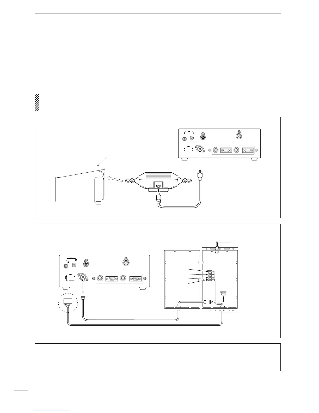
Antenna
Most stations operate with a whip or long wire (insu-
lated backstay) antenna. However, these antennas
cannot be connected directly to the transceiver since
their impedance may not be matched with the trans-
ceiver antenna connector.
R WARNING: HIGH VOLTAGE!
NEVER touch the antenna element/wire while tun-
ing or transmitting.
With a 50 matched antenna all HF bands cannot be
used. The following antenna matcher or antenna tuner
may be helpful for antenna installation.
DD
MN-100/MN-100L
ANTENNA MATCHERS
Antenna wire
MN-100/MN-100L
DD
AT-130/AT-130E
AUTOMATIC ANTENNA TUNER
[E]:
[13.6]:
[START]:
[KEY]:
to antenna element
Control cable (Not supplied from Icom)
Assemble the connector using
the supplied connector kit.
See page 61 for pin assignment.
DD
Non-Icom tuner
Some non-Icom tuners may be used with the IC-
F7000. Please consult your dealer if you wish to con-
nect one.
DD
AT-140
AUTOMATIC ANTENNA TUNER
See page 55.

Other manuals for Icom IC-F7000

Questions and Answers:

Question and Answer IconNeed help?

Do you have a question about the Icom IC-F7000 and is the answer not in the manual?

Icom IC-F7000 Specifications

General IconGeneral
BrandIcom
ModelIC-F7000
CategoryTransceiver
LanguageEnglish

Related product manuals