60
7
CONNECTION AND INSTALLATION
7
■ Fuse replacement
The transceiver has 2 fuses (2 types) to protect inter-
nal circuitry, 1 fuse for the fuse holder on the DC power
cable and 1 for inside. If the transceiver stops func-
tioning, check the fuses below.
• DC power cable ……………………………ATC 30 A
• Circuitry fuse …………………………………FGB 5 A
CAUTION:DISCONNECT the DC power cable from
the transceiver when changing a fuse.
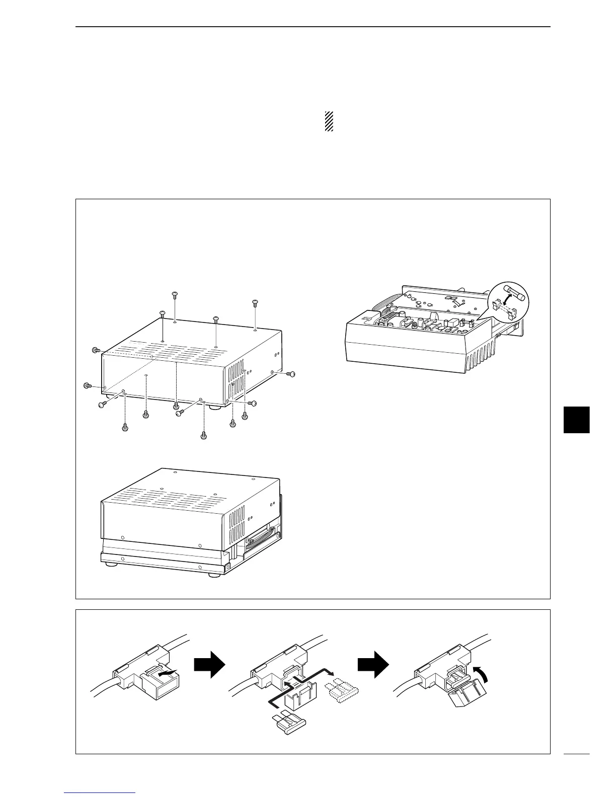
D Internal fuse replacement
q Unscrew 4 screws from the top of the transceiver
and 6 screws from the sides, then lift up the top
cover.
w Turn the transceiver upside down.
e Unscrew 6 screws from the bottom cover, then lift
up the bottom cover.
e Replace the circuitry fuse as shown in the diagram
below.
• Use the supplied FGB 5 A fuse (glass tube type).
r Replace the top and bottom covers to their original
position.
D Line fuse replacement
 Loading...