5
1
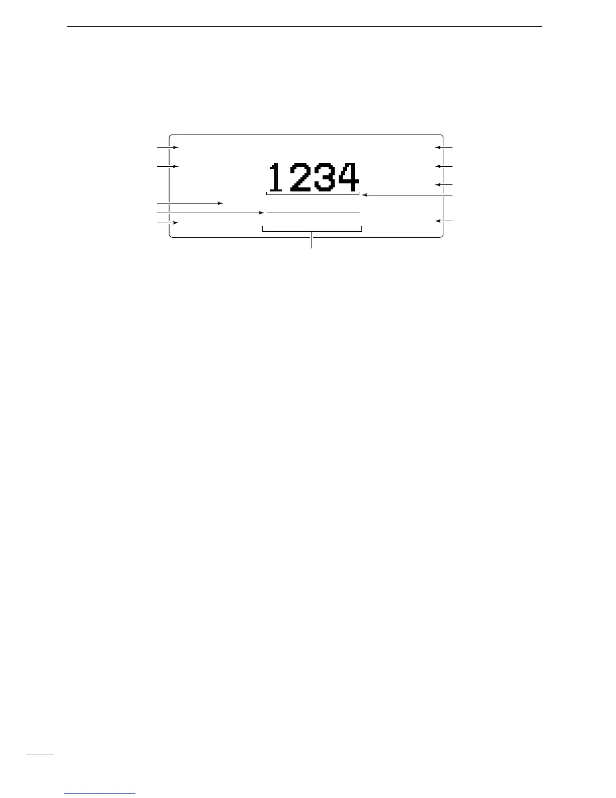
PANEL DESCRIPTION
DD
Channel indication
q COMMENT INDICATOR
➥ Shows the programmed channel comment or
comment with position data when connected GPS
receiver.
➥ Shows the condition while scanning/tuning.
•“Scanning” appears when the scan function is ac-
tivated.
•“Tuning” appears while tuning, if an optional exter-
nal antenna tuner is connected. (pgs. 55, 57)
•“Tuned” appears after the tuning is completed.
w
OPERATING MODE INDICATOR
Shows the selected operating mode.
•“USB,” “LSB,” “AM,” “CW,” “FSK,” “AFSK,” “ALE-U,”
“ALE-L” or “EMAIL” appears depending on operating
mode and setting. (Selectable mode is USB only for AUS
version.)
e TRANSMIT/RECEIVE INDICATOR
➥ “RX” appears when signals are received or the
squelch is open.
➥ “TX” appears during transmit.
r FREQUENCY INDICATOR
Shows the transmit/receive frequency of the chan-
nel. Receive frequency is displayed during recep-
tion, transmit frequency is displayed during trans-
mission. By setting the Initial set mode, both
receive/transmit frequencies can be displayed at
same time. (pgs. 14, 52)
t LQA LEVEL INDICATOR
Shows the LQA level (0–30) for displayed channel
while “ALE-U” or “ALE-L” mode is selected.
•“--”means measurement data is not available.
y S-METER INDICATOR
Shows the receiving signal strength during receive.
u SIMPLE MODE INDICATOR
“-” appears while in simple mode operation.
•While in simple mode operation, Quick set mode, Initial
set mode or etc. cannot be edited.
i TRANSMIT POWER INDICATOR
Shows the selected transmit output power.
•“HI,” “MID,” “LO” appears when the transmit power is
set to high power, middle power, low power respectively.
o MUTE INDICATOR
➥ “V” appears when the voice mute is selected.
➥ “L” appears when the Signal level mute is se-
lected.
➥ “S” appears when the call mute is selected.
!0 CHANNEL NUMBER INDICATOR
➥ Shows the selected channel number.
➥ Channel number blinks while stopping the scan.
!1 TIME INDICATOR
Shows time data.
 Loading...