3
1
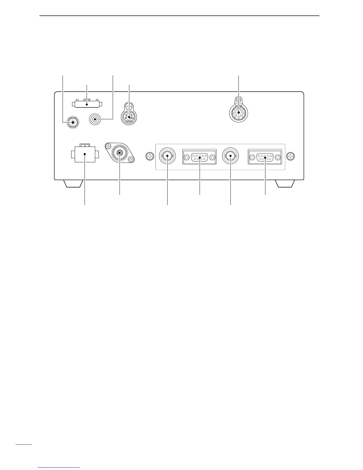
PANEL DESCRIPTION
■ Front panel— Main unit
q DC POWER SOCKET
Accepts 13.8 V DC through the supplied DC power
cable.
w ANTENNA CONNECTOR
Connects a 50 Ω HF band antenna via a 50 Ω
matched coaxial cable with a PL-259 plug for both
transmit and receive operation.
e GPS CONNECTOR [GPS]
Input position and UTC data (NMEA0183 ver. 2.0 or
3.01 format), such as from a GPS receiver for set-
ting your positioning and time data automatically.
r REMOTE CONNECTOR [REMOTE]
Connects to a PC via an RS-232C cable (D-sub 9-
pin) for remote control in the NMEA or RS-232C for-
mat.
t REFERENCE CONNECTOR [REF IN]
Connects to an external frequency oscillator for ref-
erence. Ask your technical dealer for details.
y MODEM CONNECTOR [AF/MOD]
Connects to an e-mail modem, NBDP (Narrow
Band Direct Printing) or FAX system.
u ACCESSORY CONNECTOR [ACC]
Connects a CW keyer or an FSK terminal unit, etc.
i CONTROLLER CONNECTOR [CONTROLLER]
Connects the supplied remote controller, RC-26.
o SPEAKER JACK [EXT SP]
Connects the supplied external speaker, SP-25.
!0 TUNER CONTROL SOCKET
Connects a control cable to an optional antenna
tuner.
A female connector kit is supplied for external an-
tenna tuner connection.
!1
GROUND TERMINAL
IMPORTANT! Connects a ground.
 Loading...