62
7
CONNECTION AND INSTALLATION
7
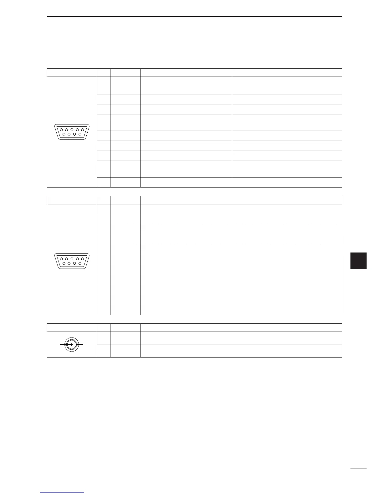
AF/MOD Pin Pin name Description Specification
1 MOD+ Modulation input (unmatched) Input impedance : 150 Ω
from an external terminal unit. Input level : Approx. 0.1 V rms.
2 MOD– Coaxial ground for MOD+.
3 GND Ground for digital equipment.
4 NAF+ AF detector output (unmatched) Output level : More than 0.774 V rms
for an external terminal unit.
5 NAF– Coaxial ground for NAF+.
6 GND Ground for digital equipment.
7NCNo connection.
8 SEND Transmits when grounded. Output level : –0.5 to 0.8 V
Input level : Less than 20 mA
9 GND Ground for digital equipment.
REMOTE Pin Pin name Description
1 DCD Input terminal for carrier detection.
2 RXD Input terminal for receive data. (“RS-232C” selection for REMOTE I/F. (p.43))
NMEA-OUT
NMEA0183 ver. 3.01 data output. (“NMEA” selection for REMOTE I/F. (p. 43))
3 TXD Outputs transmit data. (“RS-232C” selection for REMOTE I/F. (p. 43))
NMEA-IN NMEA0183 ver. 3.01 data input. (“NMEA” selection for REMOTE I/F. (p. 43))
4 DTR Outputs data terminal ready signal.
5 GND Connected to the ground.
6 DSR
Input terminal for data-set-ready signal.
7RTS Outputs request-to-send data.
8 CTS Input terminal for clear-to-send data.
9NCNo connection.
GPS Pin Pin name Description
1 NMEA + NMEA0183 ver 2.0 or 3.01 data input +.
2 NMEA _ Ground for NMEA data.
■ Connector information (continued)
 Loading...