Auxiliary Outputs
The auxiliary outputs (V- V+) of the controller can be used to supply other equipment. Note that there is no
onboard regulation or isolation for these outputs; they are a fused feed-through from the N+ N- input terminals.
When using these outputs to supply other devices, be sure not to exceed the rating of the internal fuses as
outlined in the Technical Specifications.
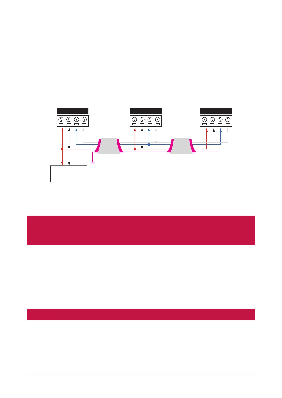
Encrypted Module Network
The controller incorporates encrypted RS-485 communications technology. Connection of the communications
should be performed according to the following diagram.
PSU or
equivalent 12V DC
Shield is frame
grounded at
one point
Shields are
connected together
and Isolated
Shielded Cable
Controller Network Module Network Module
Shielded Cable
Shield not
connected
supply
NAN+ N- NB
NAN+ N- NB
NAN+ N- NB
Always connect the controller's NA and NB terminals to the NA and NB terminals of the expansion devices and
keypads. The N+ and N- must connect to a 12V power supply source capable of supplying the peak current drawn
by all modules. If a shielded cable is used, the shield must be connected at only one end of the cable. DO NOT
connect a shield at both ends.
The 12V N+ and N- communication input must be supplied from only one point. Connections from more than
one 12V supply may cause failure or damage to the unit or the device supplying network power. Make sure that
the power supply can supply enough current for the peak load drawn by all modules connected to the 12V
supply, including the controller itself.
Module Wiring
The recommended module network wiring specifications are:
⦁ Belden 9842 or equivalent
⦁ 24AWG twisted pair with characteristic impedance of 120 ohm
⦁ Maximum total length of cable is 900m (3000ft)
⦁ CAT5e / CAT6 are also supported for data transmission when using ground in the same cable (to a maximum
length of 100m (328ft))
Warning: Unused wires in the cable must not be used to carry power to other devices.
PRT-CTRL-DIN | Protege GX DIN Rail Integrated System Controller | Installation Manual 15